Apparatus for the damped positioning of a piston

Inactive Publication Date: 2000-07-11
FESTO AG & CO KG
View PDF7 Cites 27 Cited by
  • Summary
  • Abstract
  • Description
  • Claims
  • Application Information

AI Technical Summary

Benefits of technology

One object of the invention is accordingly to create an apparatus with an improved regulation

Problems solved by technology

However, it has been seen from experience that such braking is extremely hard to perform

Method used


Image

  • Apparatus for the damped positioning of a piston
  • Apparatus for the damped positioning of a piston

Examples


Embodiment Construction

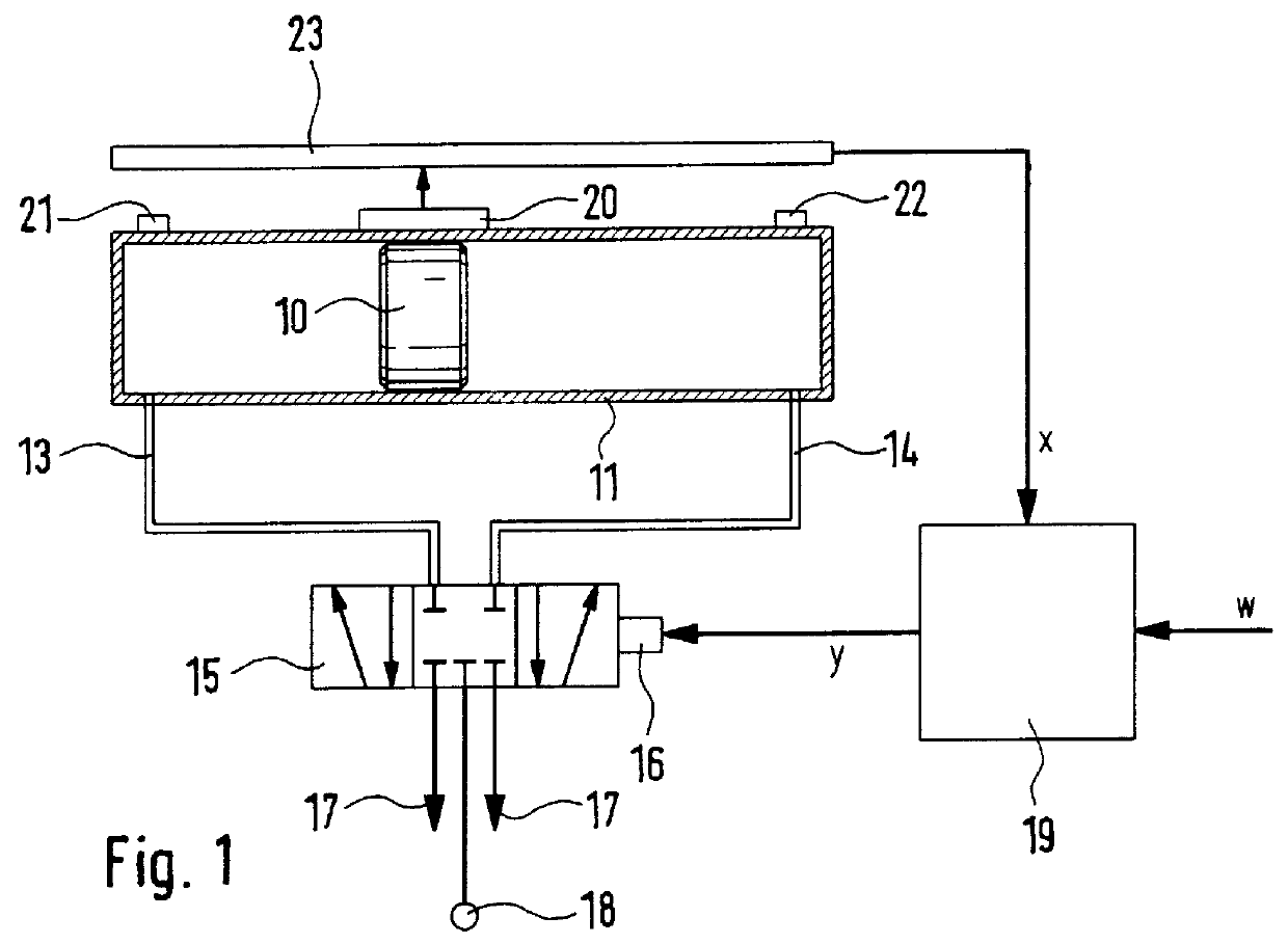
In the case of the embodiment of the invention diagrammatically illustrated in FIG. 1 a piston 10 is adapted to run in a double acting cylinder 11. From both ends of the cylinder 11 pressure lines 13 and 14 extend leading to a 5 / 3 proportional valve 15, which for setting a clearance cross section corresponding to an analog electrical input signal possesses a corresponding actuating member 16 at the outlet of the valve. In the neutral position illustrated the two pressure lines 13 and 14 are connected with venting lines 17. A source 18 of pneumatic or hydraulic pressure is in this neutral position separated from the cylinder 11.

The setting of the valve position is performed and, respectively, regulated with the aid of an electronic regulating means 19. In the one setting direction there is a displacement of the piston by the action of pressure on the one side of the piston in the one direction and in the other direction of setting by the action of pressure on the other side of the pi...


PUM


Abstract

An apparatus for the damped positioning of a piston running in a cylinder at one fixed abutment at least and more particularly for setting in a terminal position. The apparatus includes sensor means connected with an electronic regulating means for detecting the piston position as an actual value signal. A valve means adapted to be regulated by the regulating means serves for regulated braking of the piston prior to reaching the respective desired position by influencing opposing pressure in the cylinder outlet side. For forming the setting quantity for the proportional valve a position regulating means is provided which is modified by a value dependent on the respective speed and/or acceleration of the piston. This apparatus ensures an extremely accurate regulation of position simply by detecting of the position of the piston as an actual value signal. It is more particularly possible to brake the piston in the terminal positions with a damping action that an additional damping system is no longer necessary.

Description

The invention relates to an apparatus for the damped positioning of a piston running in a cylinder at one fixed abutment at least and more particularly for setting in a terminal position, comprising sensor means connected with an electronic regulating means for detecting the piston position as an actual value signal and with a valve arrangement adapted to be regulated by the regulating means for regulated braking of the piston prior to reaching the respective desired position by influencing opposing pressure in the cylinder outlet side.THE PRIOR ARTIn the case of a device of this type disclosed in the German patent publication 4,201,464 C2 the desired variations in speed are preset in order to produce the desired braking action prior to reaching the desired position. However, it has been seen from experience that such braking is extremely hard to perform with the desired speed and with a reasonable amount of complexity of the regulation means.SHORT SUMMARY OF THE INVENTIONOne object...

Claims


Application Information

Patent Timeline
IPC IPC(8): F15B11/00F15B11/048
CPCF15B11/048F15B2211/30525F15B2211/327F15B2211/6336F15B2211/665F15B2211/755
Inventor STOLL, KURTGOMMEL, GERHARDARBTER, JURGENSCHWENZER, REINHARD
Owner FESTO AG & CO KG
Why Eureka
Try Eureka