Method of controlling a welding process and controller therefor

a welding process and controller technology, applied in the field of controlling a welding process and a controller therefor, can solve the problems of no procedure in the art which controls a d.c. welding process ad hoc, high voltage of plasma arc welding, complicated process of electric arc welding, etc., and achieve the effect of facilitating the determination of spatter events

Inactive Publication Date: 2000-07-11
LINCOLN GLOBAL INC
View PDF6 Cites 57 Cited by
  • Summary
  • Abstract
  • Description
  • Claims
  • Application Information

AI Technical Summary

Benefits of technology

In counting the spatter events in the range of rates used in the present invention, both a globular transfer or a short occasionally occur. Thus, these sporadic negative spikes are counted as "spatter events." This procedure facilitates determination of spatter events in a practical sense.
In accordance with another aspect of the invention, there is provided a method of controlling in real time a D.C. electric arc welding process, as defined above, which process maintains the rate of spatter events at a desired rate. This control of the total welding process, not the wire, maintains the welding process at a specific voltage between spray transfer and globular transfer that assures repeated duplicative results in welding, irrespective of shifts and changes in the parameters dictating the operation and performance of the welding process.
Still a further object of the present invention is the provision of a method and apparatus or controller, as defined above, which method and apparatus or controller maintains a D.C. electric arc welding process with very little smoke and no spatter. In addition, the weld profile or bead is smooth, continuous and concave to accumulate slag along the axial center of the weld bead as opposed to the intersection of the edges of the weld bead and the workpiece as found in constant voltage welding. This allows easy and complete slag removal and facilitates successful multi-pass welding. The bead also has an excellent depth of penetration.

Problems solved by technology

Electric arc welding is a complicated process and the resulting deposition of molten metal into a weld pool for performing the welding operation is determined by a tremendous number of interrelated and non-interrelated parameters.
There is no procedure in the art which controls a D.C. welding process ad hoc without the intervention of the welder or welding engineer.
However, the high voltage of the plasma arc welding as shown in FIG. 1 generates excessive heat and electromagnetic radiation.
This produces a somewhat "dirty" welding process and is not considered to be optimum for the D.C. welding procedure.
When this happens, the arc is extinguished and the wire heats up and explodes.
Consequently, great voltage instability occurs immediately after the short and the break referred to as a "neck" before the electric arc or plasma is again established.
These processes create chaotic action in the molten metal forming the weld puddle.
When actually in the short circuit mode of operation, the wire or electrode shifts up and down so that the molten metal on the end of the advancing wire causes a short circuit.
Repeated short circuit and / or globular transfer operations of the welder causes drastic variations in the arc voltage of the D.C. arc welding process.
The use of a constant voltage which is high for spray transfer, as shown in FIG. 1, or is low for globular or short circuit transfer, as shown in FIG. 2, presents unwanted welding results so welding is to be performed in the specific area between spray transfer and globular transfer; however, the many variables in the welding process change the voltage defining this area for a weld process.
If a voltage is set for one group of variables, the weld process is not optimum when one or several of these variables change.

Method used


Image

  • Method of controlling a welding process and controller therefor
  • Method of controlling a welding process and controller therefor
  • Method of controlling a welding process and controller therefor

Examples


Embodiment Construction

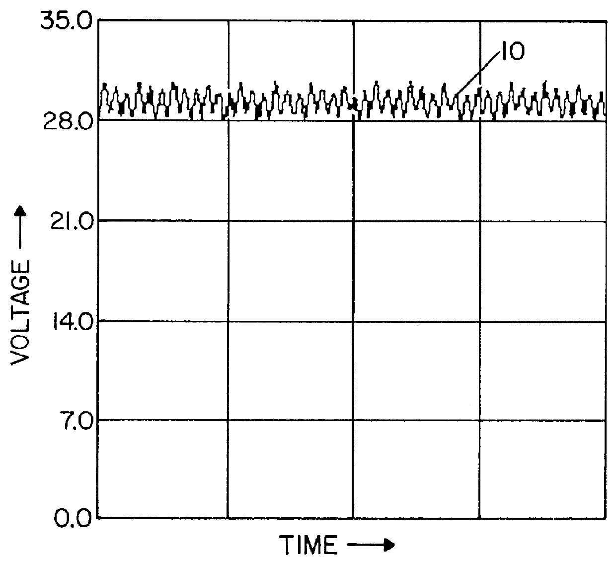
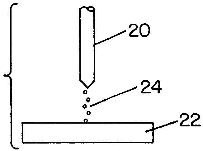
Referring now to the drawings wherein the showings are for the purpose of illustrating preferred embodiments of the invention only and not for the purpose of limiting same, FIG. 1 is a trace showing the actual arc voltage, in real time with high frequency filtered out, of a D.C. electric arc welding process schematically illustrated in FIG. 1A wherein the advancing welding wire or electrode 20 progresses toward workpiece 22. Arc voltage trace 10 across the wire and workpiece, is a high voltage, illustrated as about 29 volts, and, thus, creates a spray 24 of metal through the arc or plasma between the welding wire and the workpiece. By maintaining the arc voltage high, the voltage is relatively constant and produces a ripple trace at a constant arc voltage. This high voltage exhibits very little deviation from the set constant voltage and only exhibits a slight amount of welding noise. There are no apparent significant voltage deflections. The mode of metal transfer under this type o...


PUM

PropertyMeasurementUnit
arc voltageaaaaaaaaaa

Abstract

A controller and method for adjusting an output welding parameter of a D.C. electric arc welder for controlling a welding process wherein a welding wire is advanced toward a workpiece while an arc voltage is applied across the advancing wire and the workpiece, the control and method comprise measuring the rate of spatter events and then adjusting the output parameter to maintain the measured rate of spatter events at a selected rate in the range of 10-30 spatter events per second.

Description

The invention relates to the field of electric arc welding wherein a welding wire is advanced toward a workpiece while a D.C. arc voltage is applied across the advancing wire and the workpiece for the purpose of melting the wire and depositing the molten metal onto the workpiece and more particularly to a method of controlling the welding process and a controller for practicing the method.INCORPORATION BY REFERENCETo determine the consistency of a welding wire to be used in automatic arc welding, a spatter voltage parameter has been measured for the particular wire. If testing of the spatter voltage of a wire shows a voltage within a selected range, the quality and consistency of the wire is assured. The wire evaluation procedure is taught in Kramer U.S. Pat. No. 5,369,243 disclosing certain concepts employed in the present invention. This prior patent is incorporated by reference herein to teach certain concepts applicable to the present invention; however, the prior patent relates...

Claims


Application Information

Patent Timeline
Patent Type & Authority Patents(United States)
IPC IPC(8): B23K9/095
CPCB23K9/095
Inventor KRAMER, ARTHUR
Owner LINCOLN GLOBAL INC
Why Eureka
Try Eureka