Cut-out brush for electric hand tool

a technology of electric hand tools and cutting-out brushes, which is applied in the direction of current collectors, dynamo-electric machines, electrical apparatus, etc., can solve the problems of inability to extend even nearly as far as the known carbon brush, and inability to meet the needs of us

Inactive Publication Date: 2000-07-11
ROBERT BOSCH GMBH
View PDF11 Cites 65 Cited by
  • Summary
  • Abstract
  • Description
  • Claims
  • Application Information

AI Technical Summary

Problems solved by technology

As a result, the known carbon brush has the disadvantage that it does not extend even nearly as far as the structural height of the pressure element or contact-pressure spring, or in other words as far as the axially farthest outward region thereof.
Thus the region of the carbon brush that determines the service life of the carbon brush is relatively short, and thus the service life of the carbon brush is also relatively short.
The outer diameter, determined by the position and size of the contact-pressure spring, of the electric motor equipped with the corresponding carbon brushes, and the corresponding housing region of the manual electric machine tool equipped with such a motor, is relatively large and is ...

Method used


Image

  • Cut-out brush for electric hand tool
  • Cut-out brush for electric hand tool
  • Cut-out brush for electric hand tool

Examples


Embodiment Construction

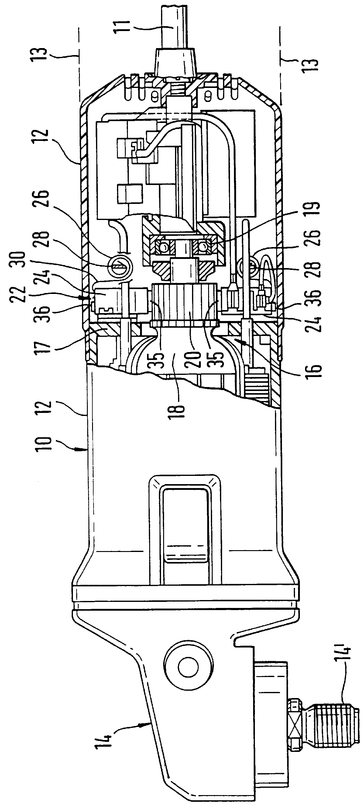
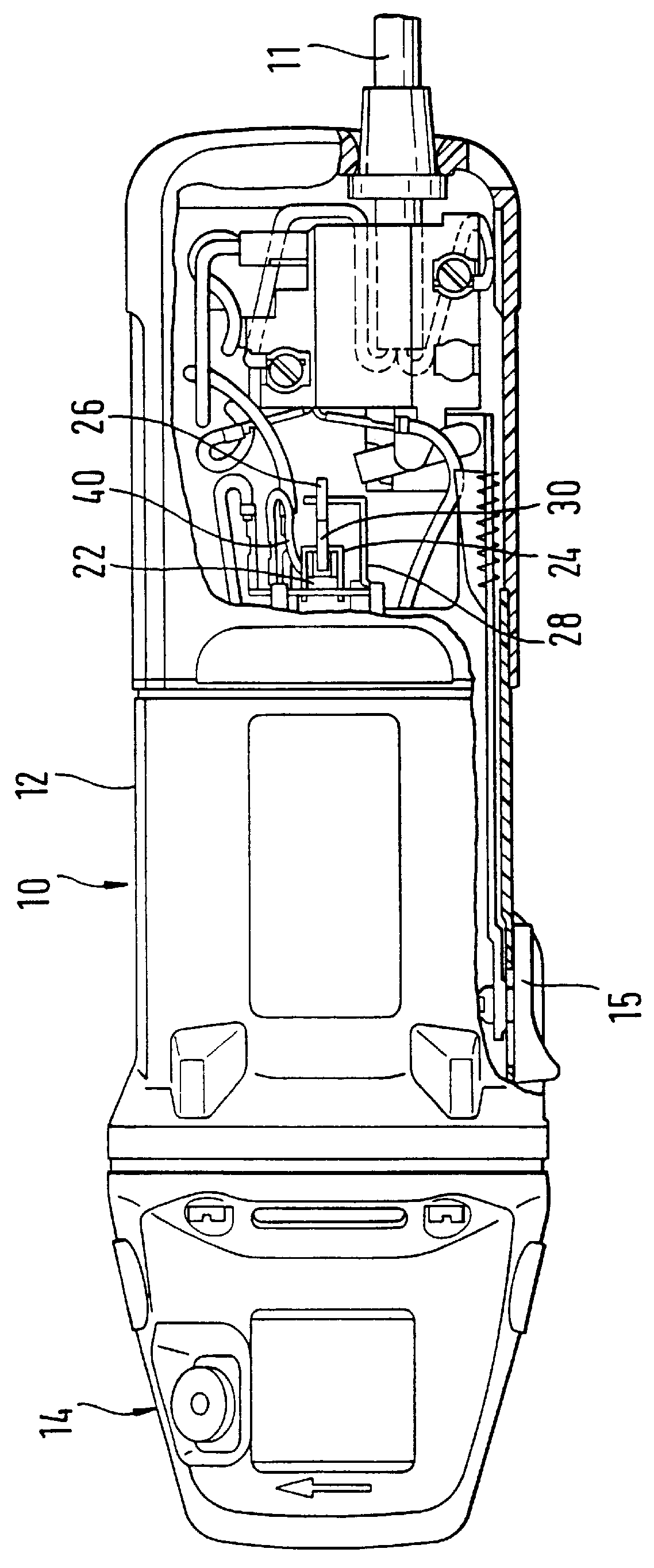
The manual electric machine tool shown in FIG. 1 is a right angle grinder 10, from behind whose motor housing 12 an electric connection cable 11 emerges; the outer contour 13 of the motor housing 12 is emphasized on opposite sides by a dashed line in each case, to show the relatively small outside diameter of the motor housing 12.

A gear housing 14 is flanged to the front of the motor housing 12 and has a power takeoff shaft 14' emerging at the bottom perpendicular to the axis of the motor housing. On the side, the motor housing 12 has a switch 15 for turning an electric switch that controls the motor on and off.

In the interior of the motor housing 12, a motor 16 can be seen, with a rotor 18 whose rear bearing 19 is braced centrally in the rear region of the motor housing 12.

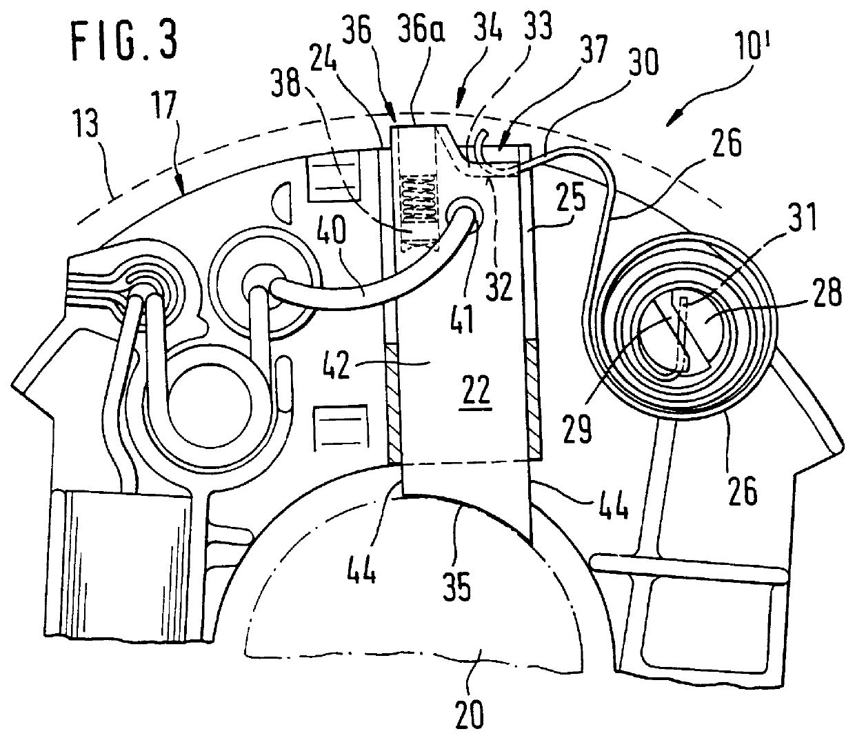
Axially adjacent to the rear bearing 19, the rotor 18 has a commutator 20, on which radially elongated carbon brushes 22 of rectangular cross section are braced elastically; they are held in carbon brush guides 2...


PUM


Abstract

PCT No. PCT/DE98/02077 Sec. 371 Date Apr. 20, 1999 Sec. 102(e) Date Apr. 20, 1999 PCT Filed Jul. 23, 1998 PCT Pub. No. WO99/13538 PCT Pub. Date Mar. 18, 1999A manual electric machine tool (10), having an electric motor (16), whose commutator (20) can be connected to a voltage source via at least one carbon brush (22) pressed against the commutator (20) by spring means (26), wherein the carbon brush (22) includes a head part (34) and a foot part (35) and has an electric pigtail lead (40) and a turn-off device (38), which at a certain wear of the foot part (35) of the carbon brush (22) automatically disconnects the electrical connection between the voltage source and the commutator (20), gains a longer useful life between service intervals for changing carbon brushes in that the carbon brush (22) is lengthened in the region of its head part (34) by a single axial continuation (36), which serves as a socket for the turn-off device (38) and is dimensioned such that the spring (26) enter flush and integrally into the outer contour of the carbon brush (22) between the outermost outer edges of the head part (34) and of the continuation (36), inside these outer edges.

Description

PRIOR ARTThe invention is based on a manual electric machine tool as generically defined by the preamble to claim 1.From German Published, Non-Examined Patent Application DE-OS 43 21 475, a carbon brush for direct current electric motors is known, which in the region of its head part has two axial, stepped continuations that each act as a socket for one current-carrying pigtail lead. Between the continuations, a bearing face of fabric-base laminate for a pressure element and a damping overlay located beneath it is provided; the pressure element is intended to press the carbon brush against the commutator. The continuations protrude axially past the bearing face for the pressure element by only approximately 5% of the total length of the carbon brush. As a result, the known carbon brush has the disadvantage that it does not extend even nearly as far as the structural height of the pressure element or contact-pressure spring, or in other words as far as the axially farthest outward re...

Claims


Application Information

Patent Timeline
IPC IPC(8): H01R39/00H01R39/38H01R39/58
CPCH01R39/381H01R39/58
Inventor BERGER, GUENTHER
Owner ROBERT BOSCH GMBH
Why Eureka
Try Eureka