Grating transducer for acoustic touchscreens

a touchscreen and transducer technology, applied in the field of ultrasonic transducers, can solve the problems that the bulk wave mode itself is unsuitable for touchscreen use, and achieve the effects of improving environmental resistance, low acoustic propagation velocity, and improving front surface clearan

Inactive Publication Date: 2000-07-18
ELO TOUCH SOLUTIONS INC
View PDF28 Cites 330 Cited by
  • Summary
  • Abstract
  • Description
  • Claims
  • Application Information

AI Technical Summary

Benefits of technology

The inventors of the invention have found, that when bulk waves, which may be longitudinal waves (compression waves) and / or transversal waves (shear waves), are propagated through the substrate toward a periodic perturbation structure on a surface of the substrate, the bulk waves are converted into surface bound or plate waves by means of the periodic perturbation. The surface bound or plate waves may then be employed to detect with high precision a touch position (a contact position or an input position) in a touch-sensitive region of the panel, which, for example, may correspond to a display area of the panel, thus alleviating the need for a wedge-type transducer. In a typical embodiment, the waves are generated by a compression mode acoustic wave transducer on one surface of the substrate, which generates a bulk wave in the substrate, directed toward a grating or set of scattering elements. Surprisingly, while grating transducers themselves have significant coupling to parasitic waves in the substrate, the inventors have found parasitic-signal effects to be quite manageable for a complete touchscreen incorporating grating transducers.
It is still another object according to the present invention to provide transducers which produce converging acoustic waves or provide other focusing or acoustic-lens functionality.

Problems solved by technology

Typically, bulk wave modes themselves are unsuitable for use in touchscreens, and must be converted to more useful wave modes.

Method used


Image

  • Grating transducer for acoustic touchscreens
  • Grating transducer for acoustic touchscreens
  • Grating transducer for acoustic touchscreens

Examples


example 1

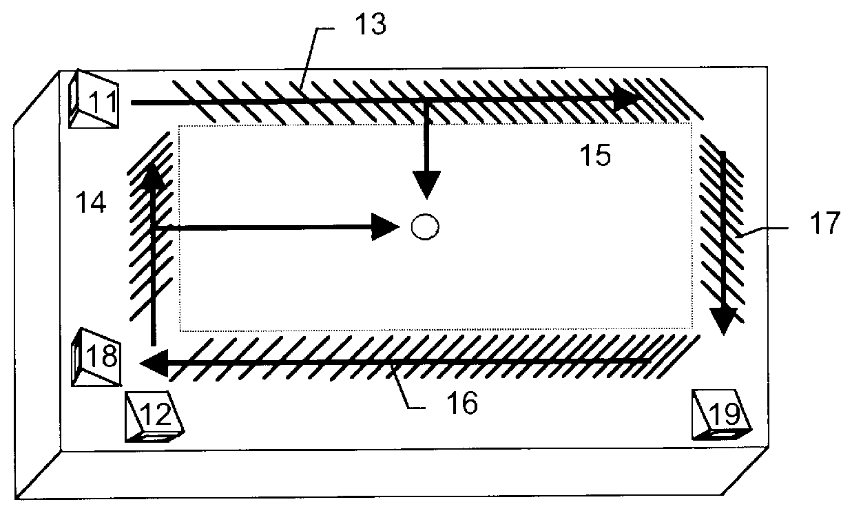
FIG. 5 is a schematic perspective view showing one embodiment of a coordinate input device according to the present invention. FIG. 6 is a schematic perspective view for illustrating a perturbation region or diffraction region by means of grating.

The coordinate input device in this embodiment comprises a propagation

medium 1 having a display area 2 adapted to be touched, which is laterally symmetrical in the directions of the X-axis and the Y-axis formed on its surface, and having a surface on which surface bound or plate waves can be propagated. The medium 1 is coupled to a transmitting transducer for propagating bulk waves (which may be pressure mode or shear mode) in an oblique direction toward the surface of the propagation medium 1 from the lowermost part of the propagation medium 1 and producing surface bound or plate waves in the directions of the X-axis and the Y-axis by means of a perturbation. The X-axis transmitting means includes the piezoelectric transducer 4a, mounted o...

example 2

Touchscreens incorporating grating transducers were designed, assembled, and tested. Grating transducer touchscreens were produced that were fully functional and had production quality signals.

Only small relative amplitude parasitic signals were observed. These parasitic signals were outside the time period of the desired signal for touchscreen operation. These parasitic signals did not disrupt touchscreen system operation and can be further reduced either with time gating in the controller electronics or by including acoustic dampers on the touchscreen outside of the touch region and reflective arrays. Despite significant parasitic wave generation by the grating transducers, parasitic signals from the receive transducers are not an obstacle to the functioning of acoustic touchscreens with grating transducers.

The dimensions of the glass substrate were about 272.5 mm.times.348.7 mm.times.3 mm. The glass substrate was provided with a 45.degree. bevel on the underside for mounting piez...

example 3

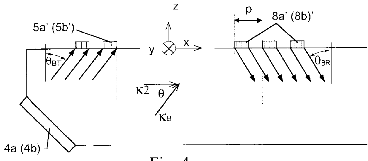
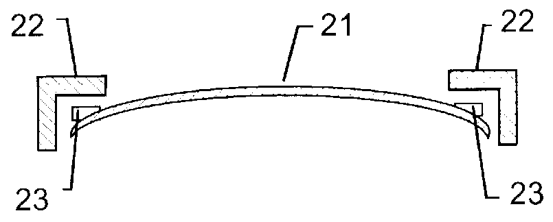
FIG. 8 shows a grating transducer adapted and applied to an acoustic touchscreen, providing a good fit for an acoustic touchscreen into an LCD touchmonitor. In FIG. 8, a bezel 26, including a seal 24, provides a barrier between the environment and the sensitive workings of the touchscreen. The front surface 22 of the substrate 20 abuts the seal 24. The seal 24 is provided to allow sufficient acoustic wave energy to permit touchscreen operation, while protecting grating 30 and piezoelectric transducer 32, as well as flat panel display 28 from contamination. The piezoelectric element 32 is bonded to a rear bevel 38 of the substrate 20, and electrically connected with solder 34 and a wire 36. The bevel is inclined at an angle .theta..sub.B with respect to a grating 30 disposed along an axis of propagation of the bulk wave emitted by the piezoelectric transducer 32 during excitation, or the axis of maximum sensitivity of the transducer to bulk acoustic waves in the substrate 20. The gra...


PUM


Abstract

An acoustic touch sensing device, comprising a substrate, having a surface; and an acoustic wave transducer, transducing a bulk wave in said substrate propagating through said substrate along an axis intersecting said surface, wherein energy of said bulk wave is coupled to a wave having a converted wave mode with appreciable energy at said surface and propagating along said surface. The device may include a set of scattering centers to couple the bulk wave to a Rayleigh wave or plate wave. The Rayleigh wave or plate wave may be dispersed over a region of the substrate, and analyzed to detect a perturbation indicative of a position of touch.

Description

TECHNICAL FIELDThe present invention relates to the field of ultrasonic transducers, and more particularly to grating transducers for acoustic touchscreens.BACKGROUND ARTTouchscreens are input devices for interactive computer systems. They are increasingly used commercially for applications such as information kiosks, order entry systems for restaurants, etc.The dominant touchscreen technologies are resistive touchscreens, capacitive touchscreens, and acoustic touchscreens. Acoustic touchscreens, i.e., ultrasonic touchscreens, are particularly advantageous when the application demands very durable touch sensitive surface and minimal optical degradation of the displayed image.Various types of ultrasonic transducers are known. The most common types used in acoustic touchscreens are wedge transducers and direct coupling between a piezoelectric transducer element and the touch substrate. A transducer is a physical element or set of elements which converts energy from one form to another...

Claims


Application Information

Patent Timeline
Patent Type & Authority Patents(United States)
IPC IPC(8): G06F3/033G06F3/043G06F3/03G06F3/041
CPCG06F3/0436G06F3/00
Inventor KAMBARA, SHIGEKIKANEDA, HIROSHIADLER, ROBERTKENT, JOELMAXFIELD, BRUCE W.TAKEUCHI, MASAO
Owner ELO TOUCH SOLUTIONS INC
Why Eureka
Try Eureka