Meander line phased array antenna element

a phased array and antenna element technology, applied in the structure of radiating elements, resonant antennas, antenna earthings, etc., can solve the problems of people miniaturizing antennas, inconvenient mounting of big antennas on cellular phones,

Inactive Publication Date: 2000-07-25
ADVANCED APPL TECH +1
View PDF5 Cites 55 Cited by
  • Summary
  • Abstract
  • Description
  • Claims
  • Application Information

AI Technical Summary

Problems solved by technology

However, a big antenna mounted on a cellular phone is inconvenient.
It has long been a problem for...

Method used


Image

  • Meander line phased array antenna element
  • Meander line phased array antenna element
  • Meander line phased array antenna element

Examples


Embodiment Construction

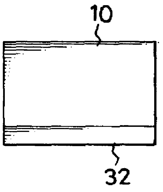
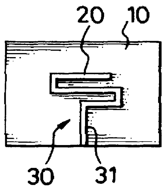
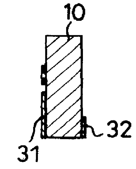
As shown in FIGS. 1 and 2, a phased array antenna element in accordance with the present invention has a dielectric plate (10) made of material with proper thickness and permittivity, such as FR-4, Mylar, ceramic or Kapton. In this embodiment, the dielectric plate (10) is made of FR-4 and is rectangular. The phased array element further has a transceiver medium component (20) securely formed on the dielectric plate (10) by means of a printed-circuit method. The transceiver medium component (20) is a meander line shape, and the dielectric plate (10) further has a microstrip line (30) also formed by the printed-circuit method so as to have electrical connection with the transceiver medium component (20) by strip line (31). Furthermore, the microstrip line (30) has a ground (32) formed on the back of the dielectric plate (10), such that the strip line (31) together with the ground (32) form the microstrip line (30) on the dielectric plate (10) for transmitting and receiving signals.

A h...


PUM


Abstract

A meander line phased array antenna element is disclosed. The phased array antenna element has a dielectric plate, a transceiver medium component formed on the dielectric plate by a printed-circuit method and a microstrip line having a strip line for electrical connection with the transceiver medium component and a ground formed on the back of the dielectric plate. Since the phased array antenna element is planar, it can be mounted on any surface, such that the quality of the transmitted and/or received signal is able to be enhanced without any influence on the size of the product using this technique.

Description

1. Field of the InventionThe present invention relates to a phased array antenna element, and more particularly to a phased array antenna element using a printed-circuit method to form a transceiver medium component and a microstrip line for electrical connection with the transceiver medium component on a side of a dielectric plate. The transceiver medium component is a meander line shape, such that not only is the size of the applied object compact, but it is also convenient to use.2. Description of Related ArtRadio transmission is a very powerful and useful method to communicate with other subjects. Through the use of radio transmissions, people can talk with distant friends or even explore the unknown in the universe. Notwithstanding in what fields radio transmission is applied, a giant, protruding antenna is one thing that is inevitable for transmitting and receiving signals with high quality. For a stationary facility, a giant antenna is not a bad thing when taking the quality ...

Claims


Application Information

Patent Timeline
IPC IPC(8): H01Q1/36H01Q1/38H01Q1/24
CPCH01Q1/243H01Q1/362H01Q1/38
Inventor PENG, SHENG-YENG
Owner ADVANCED APPL TECH
Why Eureka
Try Eureka