Support tool for deep rolling crankshaft fillets

Inactive Publication Date: 2000-08-01
HEGENSCHEIDT MFD
View PDF3 Cites 21 Cited by
  • Summary
  • Abstract
  • Description
  • Claims
  • Application Information

AI Technical Summary

Benefits of technology

The present invention seeks to overcome such problems by improving control over any tendency of the crankshaft to move laterally during fillet rolling by providing a new and improved lower crankshaft support tool which is carried by the lower jaw arm. The lower support tool includes laterally spaced large diameter annular flanges which o

Problems solved by technology

However, even with such a linkage, lateral movement may occur to such an extent that the flanks or sides of the counterweights or other adjacent portions of the crankshaft are contacted and abraded by the tools or a portion of the jaw assembly.
This may cause cr

Method used


Image

  • Support tool for deep rolling crankshaft fillets
  • Support tool for deep rolling crankshaft fillets
  • Support tool for deep rolling crankshaft fillets

Examples


Embodiment Construction

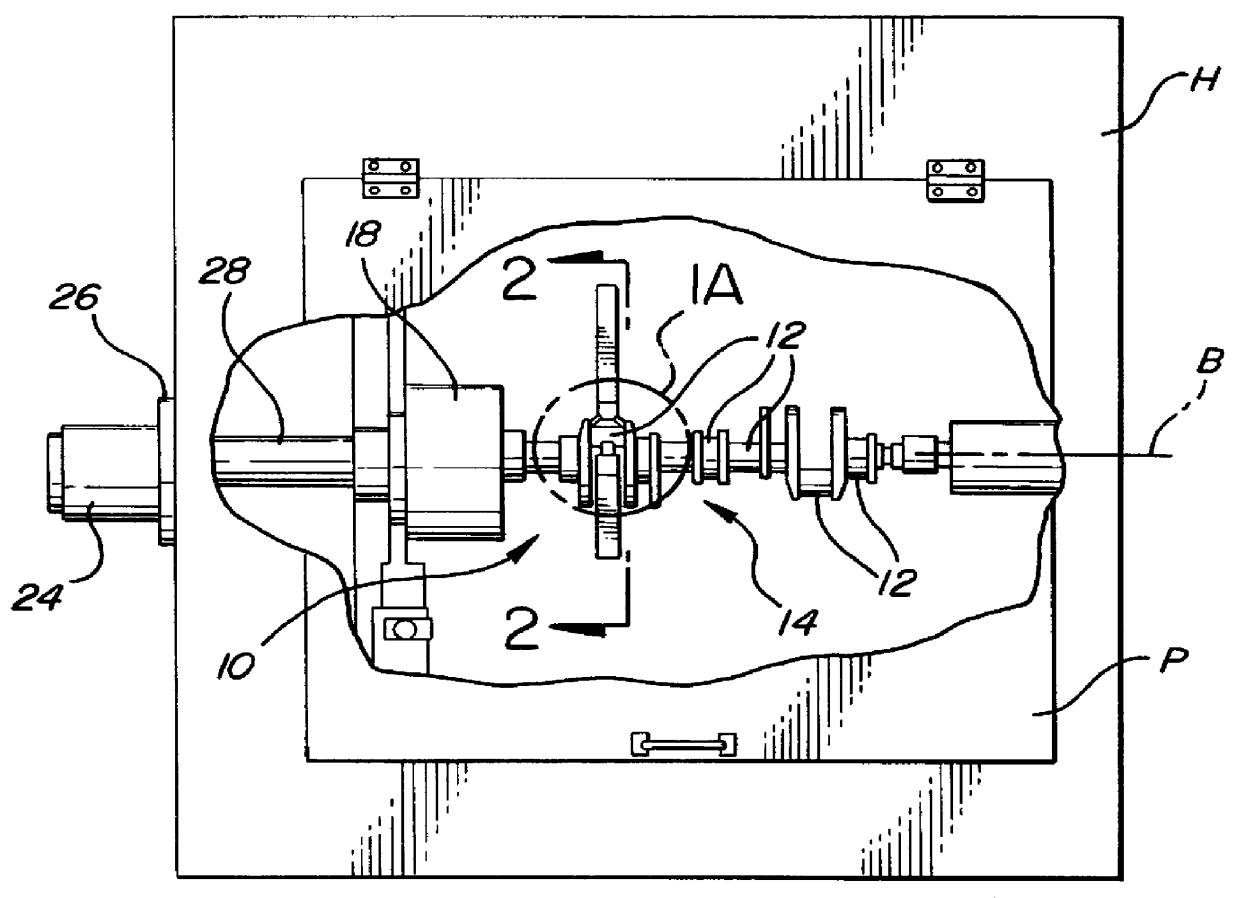
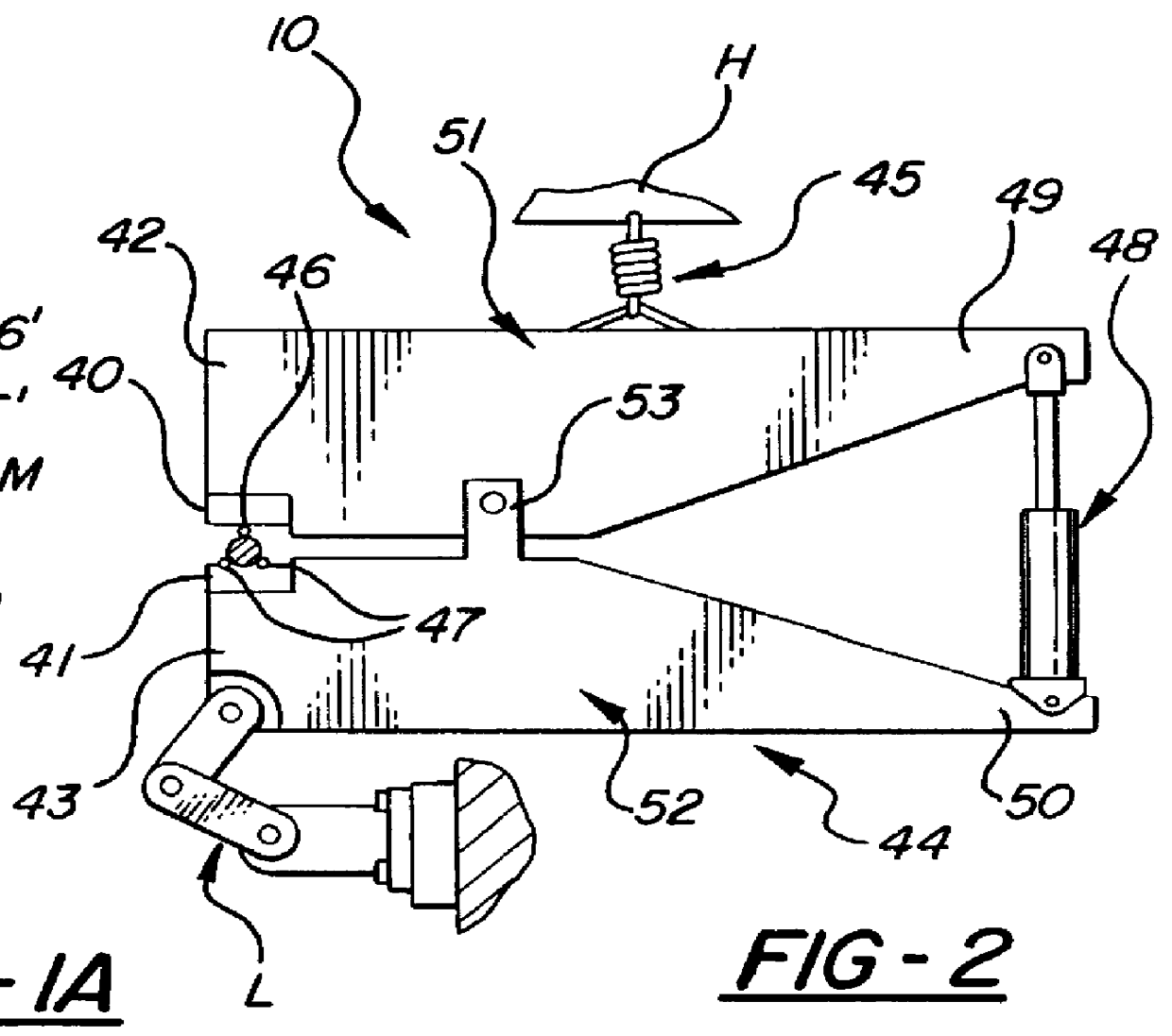
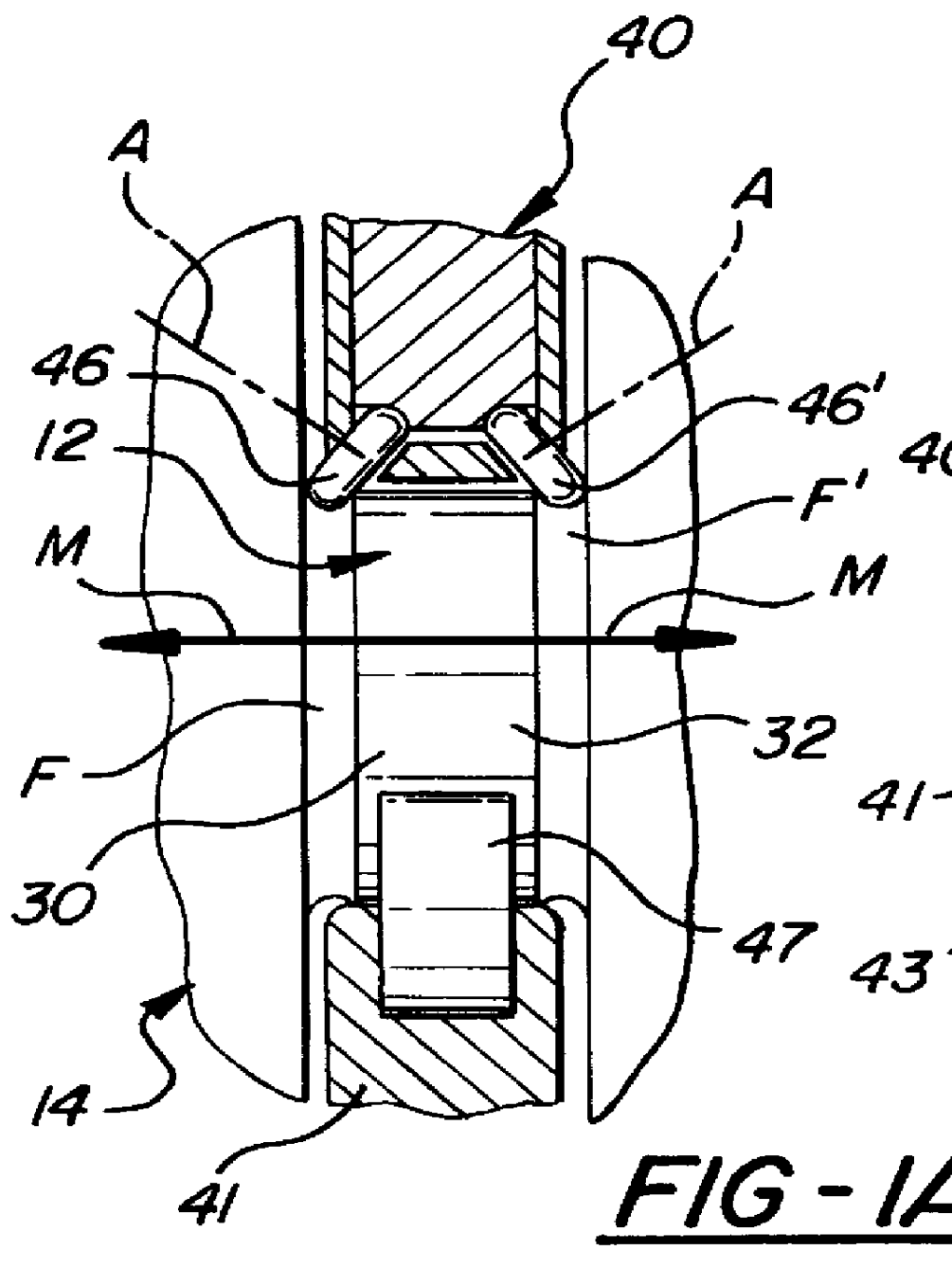
FIGS. 1 and 2 diagrammatically show portions of a metal working machine 10 illustrating some construction and principals of deep roll strengthening of the fillets of journals 12 of a crankshaft 14. The crankshaft engine can be rotatably driven about horizontal axis B by a drive motor 24 supported by a mounting collar 26 on the machine housing and drivingly connected to the chuck 18 by drive shaft 28. The pin journals for the engine pistons have side-by-side and coaxial journal portions 30 and 32 (FIG. 1A) providing cylindrical bearings for the connecting rods 34, 36 (FIG. 1B) of opposing pistons in the left and right cylinders of V-block engines.

In view of the fact that the pin journal portions 30, 32 as well as the main journals experience high stress loads during engine operation, they are strengthened in various ways such as by deep roll hardening the radii of the undercuts of the laterally spaced annular fillets F, F.sup.1 of the pin journal. Deep rolling directs high, concentra...


PUM

PropertyMeasurementUnit
Diameteraaaaaaaaaa
Radiusaaaaaaaaaa
Stress optical coefficientaaaaaaaaaa

Abstract

PCT No. PCT/US98/09524 Sec. 371 Date Jan. 15, 1999 Sec. 102(e) Date Jan. 15, 1999 PCT Filed May 13, 1998 PCT Pub. No. WO98/51432 PCT Pub. Date Nov. 19, 1998Deep rolling equipment for cold working fillet radii of annular undercuts on opposite sides of main bearing and crank pin journals of an engine crankshaft while being rotatably driven. The equipment has pairs of jaws movable between an open position for receiving the crankshaft journal and a closed position for rolling the fillets thereof. The upper jaw mounts fillet rolling tools for high load rolling engagement in the annular undercuts and a lower tool on the opposing lower jaw for support of the journal. The lower tool has a pair of support rollers with annular journal support portions which contact and support the journal while the fillet radii of the undercuts on either side of the journal are being rolled. These support rollers importantly have work stabilizing annular flanges outboard of the support portion with larger diameters that ride in the undercuts and limit lateral movement of the crankshaft with respect to the rolling and support tools so that the crankshaft is not abraded or otherwise damaged by side contact of the jaws and tools with portions of the crankshaft.

Description

The present invention relates to a lower support tool for deep rolling fillets of a crankshaft. More specifically, the invention relates to a new and improved apparatus for limiting relative lateral movement between the crankshaft and the fillet rolling is tools of a jaw assembly during rolling operation.Deep rolling of crankshaft journal fillets for crankshaft strengthening purposes is well known in the art. The journals of a crankshaft for internal combustion engines are disposed between laterally spaced counterweights formed on the crankshaft. The journal fillets are located at the intersection of the journal and the adjacent counterweight and define concentrated annular areas of high stress which must be mechanically relieved to improve crankshaft strengths in these otherwise weakened areas. Various arrangements of floating jaw units are employed at each journal to mechanically roll the fillets and relieve such stresses and strengthen them.Generally, each jaw unit has opposing u...

Claims


Application Information

Patent Timeline
IPC IPC(8): B24B39/00B24B5/42B24B39/04B24B5/00B21H7/18B21H7/00
CPCB21H7/185B24B39/045B24B5/42B21H7/182Y10T29/17
Inventor VODOPYANOV, EUGENECADENA, LUIS
Owner HEGENSCHEIDT MFD
Why Eureka
Try Eureka