Edge lifting recess former and reinforcement system

a technology of recess former and recess, which is applied in the direction of lifting devices, shaping building parts, moulds, etc., can solve the problems of cracking of the concrete adjacent to the anchorage, insufficient concrete volume to resist the applied load without failure, and the risk of concrete failure in the edge region

Inactive Publication Date: 2000-08-01
ITW RAMSET AUSTRALIA
View PDF4 Cites 5 Cited by
  • Summary
  • Abstract
  • Description
  • Claims
  • Application Information

AI Technical Summary

Benefits of technology

According to another aspect of the present invention there is disclosed an anchor device for the edge lifting of a concrete slab, said anchor device comprising an anchor element able to be partially embedded in said concrete slab, one end of said anchor element having a lifting head shaped to be positioned within a recess formed in the edge of said slab located a small distance inwardly of the lifting head, and a shear reinforcement means extending away from said lifting head and able to be partially embedded in said slab and partially positioned within said recess, wherein said reinforcement means is isolated from contact with said concrete slab in the direction of lifting of said slab thereby allowing the shear reinforcement means to deflect without compressing the concrete and to substantially transfer the load through the shear reinforcement means to the concrete slab away from a critical zone of failure so that concrete failure does not occur.

Problems solved by technology

Here there is a risk of failure of the concrete in the region of the edge as a result of the shear forces generated by the application of the force to the anchor.
Therefore there is often an insufficient volume of concrete to resist the applied load without failure.
However, when a shear load is applied i.e. force is applied at an angle to the axis of the lifting anchor, particularly where the anchor is near the edge of a precast panel, cracking of the concrete adjacent to the anchor has occurred.
While this may not represent a problem structurally, the cracking is unsightly and unacceptable architecturally.
Consequently costly patching and repair operations have been required.
The shear bar described in that patent is not effective for preventing damage to the concrete as a result of shear forces being transmitted by the lifting device to the inside surface of the recess in the concrete.
A disadvantage of the existing methods of transferring the shear loads into the concrete by using steel reinforcement bars has been that the bars have been directly embedded into the concrete and no account has been taken of the different physical properties of concrete and steel.
A further disadvantage of existing methods using shear bars is that failure of the concrete panel can occur by bursting from the edge where the anchorage extension of the shear bar extends in the same plane as the edge of the panel (normal to the anchor axis).
Cracks opened by this force can initiate a failure crack which propagates in the direction of lift.
Such cracking can occur at applied loads which are less than the loads required to cause the panel to fail in the direction of lift.

Method used


Image

  • Edge lifting recess former and reinforcement system
  • Edge lifting recess former and reinforcement system
  • Edge lifting recess former and reinforcement system

Examples


first embodiment

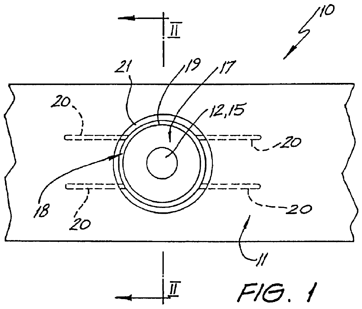
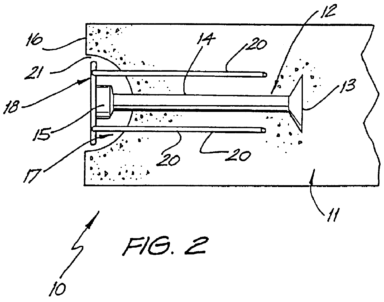
An anchor device 10 of a first embodiment for the edge lifting of a concrete slab 11 is illustrated in FIGS. 1 and 2. The device 10 includes an anchor element 12 which is embedded in the concrete slab 11. The anchor element 12 has a foot portion 13, a shank 14 and a head 15. The head 15 is shaped to co-operate with conventional slab lifting apparatus (not illustrated). The head 15 is positioned a small distance inwardly of the edge 16 of the concrete slab 11 and is positioned within a recess 17 which is formed at the edge 16 of the slab 11 when the concrete is being poured. The recess 17 is formed using known techniques and the shank 14 and foot portion 13 are embedded in the slab 11 during the concrete pour.

Shear reinforcement 18, which is a separate item from the anchor element 12, is also partially embedded in the concrete slab 11 during the pour. The shear reinforcement 18 includes a ring portion 19 from which four reinforcing bars 20 extend into the concrete slab 11. The shear ...

second embodiment

An anchor device 30 of a second embodiment is illustrated in FIGS. 3 and 4. The device 30 which is used to edge lift a concrete slab 31, includes an anchor element 32 which is embedded into the concrete slab 31. The anchor element 32 is identical to the anchor element 12 and has a foot portion 33, a shank 34 and a head 35. The head 15 is positioned inwardly from the edge 36 of the concrete slab 31 and is positioned within a recess 37. The recess 37 in this embodiment is not hemi-spherical but is truncated at both sides.

Shear reinforcement 38 includes a single bar 40 which protrudes into the concrete slab 31 perpendicularly to the anchor element 32. The bar 40 spreads the shear load during lifting into the concrete slab 31 and passes through the recess 37 substantially at its lower portion as illustrated in FIG. 3. The shear reinforcement 38 also includes a brace portion 39 which is curved and extends upwardly above the bar 40. The brace portion 39 passes from the concrete slab 31 th...

third embodiment

An anchor device 50 of a third embodiment is illustrated in FIGS. 5 and 6. The anchor device 50 is used for the edge lifting of a concrete slab 51 and includes an anchor element 52 embedded therein. The anchor element 52 has a foot 53 with a hole 53A passing therethrough. The anchor element 52 also includes a shank 54 and a head 55. The head 55 is once again shaped to co-operate with existing slab lifting apparatus and is positioned a small distance inwardly from the edge 56 of the concrete slab 51 and is positioned within a recess 57 which is similar to recess 37. Shear reinforcement 58 which is embedded in the slab 51 includes two curved bars 60. The bars 60 include legs 62 which extend into the concrete slab 51 and act as an anchor and act to disperse the shear forces. The bars 60 each include a curved portion 59 which is located within the recess 57 in a similar manner to the previously described embodiments. The curved portion 59 ensures that there is an air gap 61 between the ...


PUM

PropertyMeasurementUnit
shear loadaaaaaaaaaa
forceaaaaaaaaaa
shear forcesaaaaaaaaaa

Abstract

A recess former (130) is adapted for forming a recess (133) around the head of an anchor element (131) which is embedded in an edge of a concrete slab during casting thereof. The recess former (130) has an outer curved surface extending from a flat base surface. The outer surface has a hole at its apex to allow the anchor (131) to extend out of the recess former (130). A web (137) is located at the outer surface and has a channel (138) which is adapted for positioning of shear reinforcement means. The web (137) forming an air gap after the recess former (130) is removed from the recess.

Description

The present invention relates to reinforcing precast or cast-in-place concrete elements and is particularly concerned with arrangements to facilitate the use of lifting anchors which are partially embedded in the concrete and have a projecting portion to which a lifting device is able to be engaged.A particularly important area of application is where the lifting anchor is placed in the edge of an end or side of a thin concrete panel and where the panel is to be lifted in a direction normal to the axis of the anchor with a shear load applied to the anchor. A common application of this type exists in the construction of tilt-up buildings. In this type of construction thin wall panels are cast horizontally at ground level and raised into the vertical position by tilting the horizontal panel about one (lower) edge by lifting with anchors set in the opposite (upper) edge until it is in the vertical position. Then it is lifted into its final position to form a wall element.The invention ...

Claims


Application Information

Patent Timeline
Patent Type & Authority Patents(United States)
IPC IPC(8): E04G15/04E04G21/14E04G15/00B66F19/02
CPCE04G15/04E04G21/142
Inventor MACKAY SIM, RODNEYMETHAM, BARRY JAMES
Owner ITW RAMSET AUSTRALIA
Why Eureka
Try Eureka