Method for sucking/determining liquid and pipetting device driven and controlled according to method

a pipetting device and liquid technology, applied in the direction of process and machine control, laboratory glassware, instruments, etc., can solve the problems of low resolution, increased device size and cost, and low sensitivity

Inactive Publication Date: 2000-08-08
PRECISION SYST SCI
View PDF9 Cites 53 Cited by
  • Summary
  • Abstract
  • Description
  • Claims
  • Application Information

AI Technical Summary

Problems solved by technology

For this reason, conventionally, a method has been employed, in which an electrode is immersed in the liquid together with the nozzle and the liquid level is detected according to a conductive state with the electrode so that an inserting rate (distance) of the nozzle to the liquid is controlled, but in the case of this method, the electrode must be immersed into the liquid, so that the electrode must be washed after each measurement thereof to prevent cross contamination, and as a result, there have been such problems as that a device becomes complicated, and that size and cost of the device increase.
However, the method of detecting a liquid level using a pressure sensor has several problems such as that the resolution is low and the sensitivity is not high, and also that the method is easily affected by an atmospheric pressure as well as by pressure change due to the sucked air, and also affected by vibrations generated due to upward / downward movement of the nozzle as well as by a noise of the pipetting device itself or a change of a voltage, and for this reason malfunction thereof occurs quite often, and the reliability thereof as a measuring means is quite low.
However, in the liquid level detecting means using a light for detecting a liquid level based on the conventional technology, in which both a fiber for irradiating a light therethrough and an optical fiber for receiving a light are provided outside the nozzle for catching a reflected light from a liquid level with the optical fiber for receiving a light to detect the level thereby, these fibers have to be inserted in parallel to each other together with the nozzle into a vessel for a liquid, and for this reason it can not be denied that the method has a possibility of cross contamination caused by the fiber contacting with the liquid adhered to the wall surface of the vessel for a liquid, and also the amount of light caught by the optical fiber for receiving a light is extremely small, which makes it difficult to accurately detect a liquid level, and in addition the extremely minute control is required, which is difficult because there also occur some cases where a timing for receiving the reflected light is shifted or a light can not be received by the fact that the liquid level becomes slightly wavy due to vibrations of the device.

Method used


Image

  • Method for sucking/determining liquid and pipetting device driven and controlled according to method
  • Method for sucking/determining liquid and pipetting device driven and controlled according to method
  • Method for sucking/determining liquid and pipetting device driven and controlled according to method

Examples


first embodiment

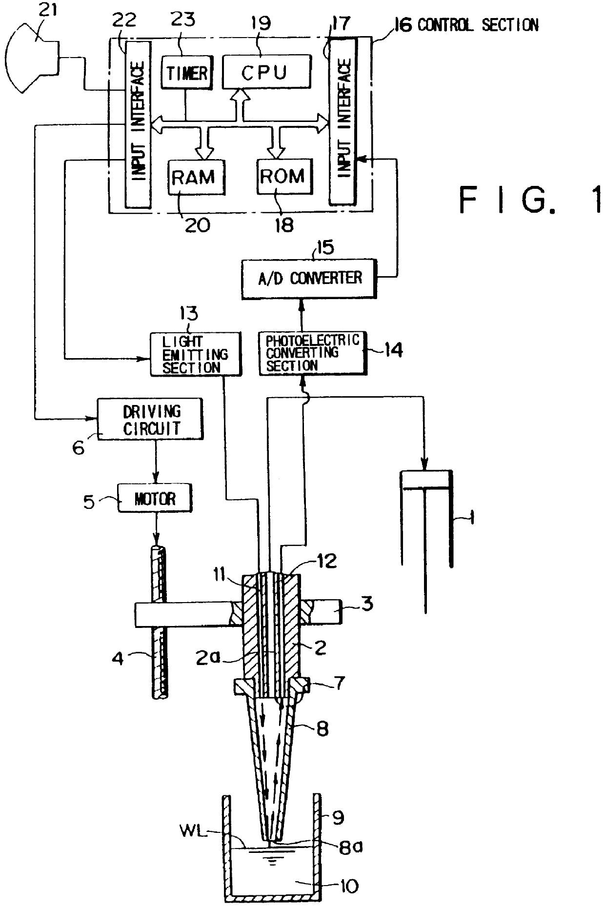
FIG. 1 shows a schematic configuration of a pipetting device to which the method for sucking / determining a liquid according to the present invention is applied, and the pipetting device basically comprises a nozzle 2 communicated with and connected to a cylinder 1; an arm 3 for holding the nozzle 2; a drive mechanism 4 for moving the arm 3 upward and downward; a motor 5 for operating the drive mechanism 4; a driving circuit 6 for controlling regular / reverse rotation of the motor 5; and a disposable tip 8 detachably attached to the lower edge section 7 of the nozzle 2.

The nozzle 2 is moved downward at a specified position by the drive mechanism, the liquid level WL is detected by a liquid level detecting mechanism described later, then a liquid 10 such as a serum or a reagent accommodated in a vessel 9 is sucked, and then the pipetting device moves upward to discharge the sucked liquid to another vessel (not shown herein). It should be noted that each of the basic configurations of t...

third embodiment

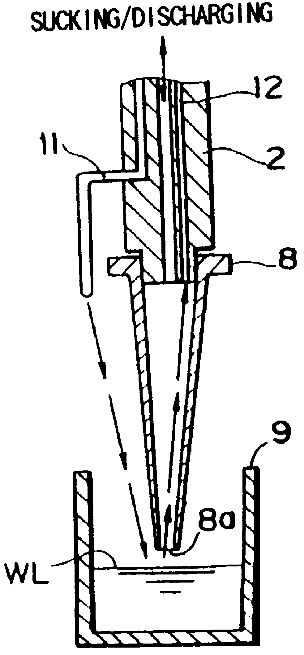
FIG. 3 shows the third embodiment according to the present invention, and in this embodiment, the device can also be constructed so that the lower edge sections of the light irradiating body 11 and the light receiving body 12 are provided in the side section of the lower edge section 7 of the nozzle 2 in the exposed state respectively, and the disposable tip 8 may be formed with a transparent and photoconductive material, and in that case a light irradiated from the light irradiating body 11 passes through the disposable tip 8 and is irradiated to the liquid surface WL through the opening section 8a at the chip of the disposable tip 8, the reflected light again passes through the disposable tip 8, and the amount of the light can be detected with the light receiving body 12.

fourth embodiment

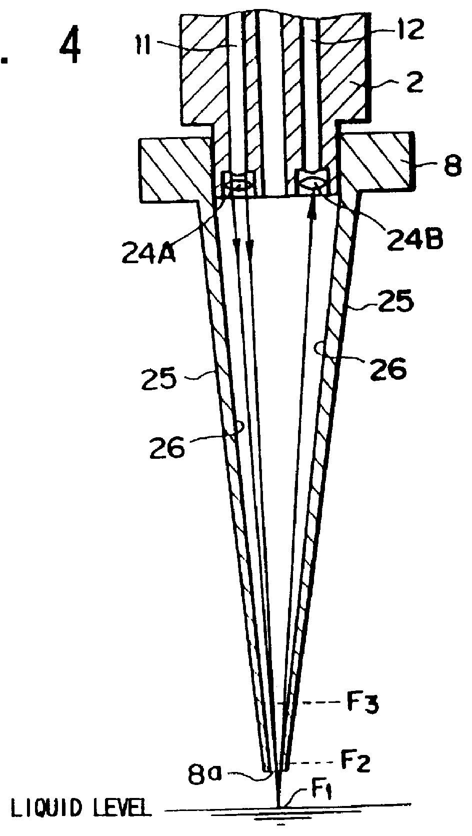
FIG. 4 shows the fourth embodiment according to the present invention, and in this embodiment, focusing lenses 24A, 24B are provided each at a positions lower than each of the lower edge sections of the light irradiating body 11 and the light receiving body 12, the light irradiated from the light irradiating body 11 is focused at a point F.sub.1 on the liquid surface WL, so that a brighter reflected light can be received, and the resolution can further be improved.

The focusing lenses 24A, 24B may be concave lenses or convex lenses, or may be a combination thereof, and also the irradiated light may be focused not only on the point F.sub.1 on the liquid surface, but also at a center portion F.sub.2 of the opening section 8a at the lower end of the disposable tip 8, or at a position F.sub.3 slightly above the opening section 8a at the lower end of the disposable tip 8 or at any other appropriate position so long as a change in a quantity of received light can be accurately detected. Th...


PUM

PropertyMeasurementUnit
transmissionaaaaaaaaaa
sizeaaaaaaaaaa
pressuresaaaaaaaaaa

Abstract

In the present invention, a disposable tip or a tip of a cleaning system is attached to a lower edge section of a nozzle, and the nozzle detects a liquid level by receiving fluctuation of a light close to the disposable tip or to an opening section at a lower end of the tip in the cleaning system, for instance, a light reflected from the liquid surface. In the present invention, not only the liquid level is detected, but also a liquid is filled in the disposable tip or the tip of a cleaning system detachably attached to the nozzle, a light is passed through the liquid in the disposable tip or the tip of a cleaning system, and a change of a light amount of the sucked liquid is detected, so that, for instance, a suction rate of the liquid, transparency thereof, contaminated by bubbles therein, clogging and a state wherein water has been exhausted are determined.

Description

The present invention relates to an entirely new method for sucking / determining a liquid and a pipetting device driven and controlled according to the method, and more particularly to a method for sucking / determining a liquid in which driving required for upward / downward movement of a nozzle for sucking a liquid such as a sample for a blood serum and a reagent as well as for pipetting a liquid to cylinders each for sucking and discharging the liquid is accurately controlled, so that a liquid level and a sucking rate of a liquid by the nozzle, and contamination of foreign matters therein such as bubbles or fibrins or the like in the liquid can accurately be detected, as well as to a pipetting device driven and controlled according to the method.Generally, important matters required for enhancing pipetting precision are to detect a level of a blood serum sample and a reagent or similar liquid, to measure a pipetting rate thereof, to measure an absolute sucking rate thereof, to adhere ...

Claims


Application Information

Patent Timeline
Patent Type & Authority Patents(United States)
IPC IPC(8): G01F23/284G01F23/292G01N35/10G01F23/28G01N1/00G01N21/11G01N21/59
CPCG01F23/292G01F23/2928G01N35/1016G01N2035/1018Y10T436/119163G01N2035/1062Y10T436/114998Y10T436/2575G01N2035/1025
Inventor TAJIMA, HIDEJI
Owner PRECISION SYST SCI
Why Eureka
Try Eureka