

Laser displacement measurement system
a displacement measurement and laser technology, applied in the direction of distance measurement, instruments, using reradiation, etc., can solve the problems of system accuracy decline, ambiguity in determining the absolute range (i.e. distance to target), and difficulty in obtaining the actual range of the target, etc., to achieve simple design and low cost
- Summary
- Abstract
- Description
- Claims
- Application Information
AI Technical Summary
Benefits of technology
Problems solved by technology
Method used
Image

Examples
example 1
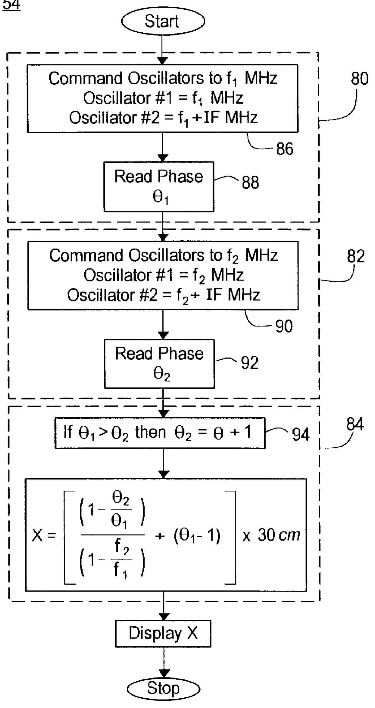
The step of determining the first phase difference 80 commands the oscillators 86 to 1000.00 Mhz and 1004.50 Mhz. Reading step 88 determines the first phase difference, .theta..sub.1, to be 0.75 cycles. The step of determining the second phase difference 82 then commands the oscillators 90 to 1010.10 Mhz and 1014.60 Mhz and reading step 92 determines the second phase difference, .theta..sub.2, to be 0.7725 cycles. The step of incrementing the second phase difference 94 determines that the first phase difference (0.75) is less than the second phase difference (0.7725) and, therefore, does not increment the second phase difference by one. These phase difference and frequency values are then used in Equation 1 to determine the absolute range of the target as follows: ##EQU2## x=[2.72].times.30 cm x=81.60 cm
example 2
The step of determining the first phase difference 80 commands the oscillators 86 to 1000.00 Mhz and 1004.50 Mhz. Reading step 88 determines the first phase difference, .theta..sub.1, to be 0.99 cycles. The step of determining the second phase difference 82 then commands the oscillators 90 to 1010.10 Mhz and 1014.60 Mhz and reading step 92 determines the second phase difference, .theta..sub.2, to be 0.0197 cycles. The step of incrementing the second phase difference 94 determines that the first phase difference (0.99) is indeed greater than the second phase difference (0.0197) and, therefore, increments the value of the second phase difference by one for a total of 1.0197 cycles. These phase difference and frequency values are then used in Equation 1 to determine the absolute range of the target as follows: ##EQU3## x=[2.96].times.30 cm x=88.80 cm
The basis for the step of incrementing the second phase difference 94 is to compensate for phase shift greater than one complete cycle, wh...
PUM
 Abstract
Description
Claims
Application Information