Floatable auxiliary fuel tank

Inactive Publication Date: 2000-08-15
LESESNE EDWARD R
View PDF9 Cites 27 Cited by
  • Summary
  • Abstract
  • Description
  • Claims
  • Application Information

AI Technical Summary

Problems solved by technology

Yachts, pleasure boats, work boats, and other small water craft have limited fuel capacities.
Unfortunately, the boat's large fuel capacity is offset by a high rate of fuel consumption.
Unfortunately, these containers occupy precious deck space on the vessel

Method used


Image

  • Floatable auxiliary fuel tank
  • Floatable auxiliary fuel tank
  • Floatable auxiliary fuel tank

Examples


Embodiment Construction

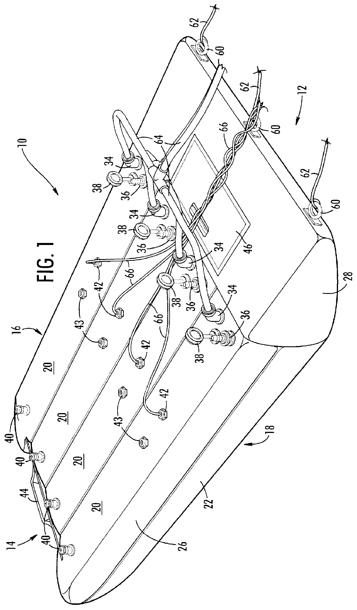
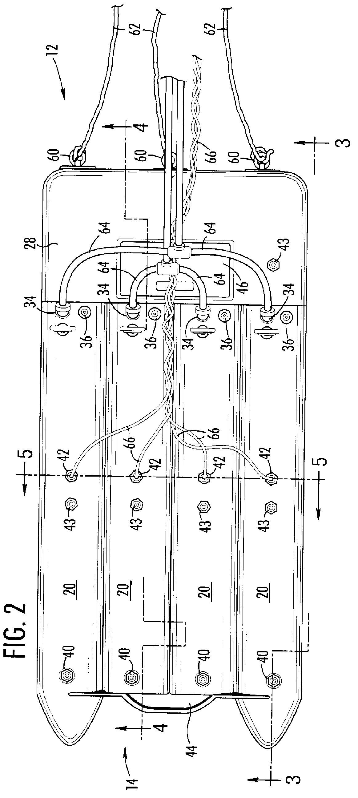
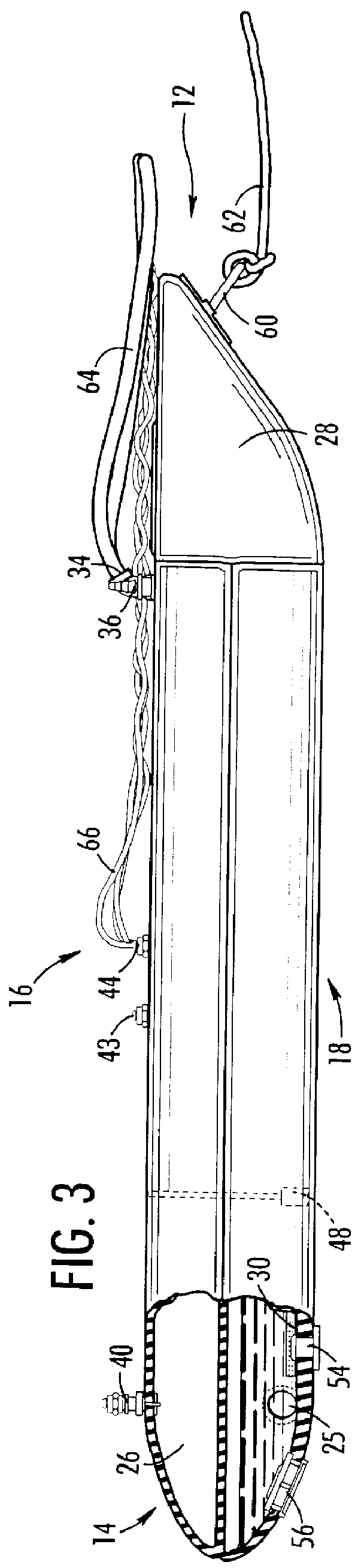
Referring now to the figures, the present invention is a floatable fuel tank that is capable of serving as a barge or lifeboat / dingy. The term barge means a cargo-carrying vessel that is towed behind a boat, while a lifeboat / dingy is a small water-craft that may serve as a boat in emergency situations or transportation in normal situations. For purposes of orientation, the tank, generally referred to by reference number 10, has a bow 12, a stern 14, a top 16 and a bottom 18. Tank 10 comprises a plurality of bladders 20 with each having a fuel chamber 22 and air chamber 26 running longitudinally from stern to a forward bladder 28. If used as a fuel storage device, tank 10 is attached to boat 2 using towing lines 62 and fuel lines 64 so boat 2 consumes fuel held by fuel chambers 22 as illustrated in FIG. 6. In emergency situations, tank 10 is capable of use as a lifeboat by detaching towing lines 62, fuel lines 64, and air lines 66 and pumping fuel out of fuel chambers 22 with air so ...


PUM


Abstract

A floatable fuel tank that is capable of serving as a barge or lifeboat/dingy. Tank comprises a plurality of bladders with each having a fuel chamber and air chamber running longitudinally from stern to a forward bladder. If used as a fuel storage device, tank is attached to boat using towing lines and fuel lines so boat consumes fuel held by fuel chambers. In emergency situations, tank is capable of use as a lifeboat by detaching towing lines, air lines and fuel lines and pumping fuel out of fuel chambers with air so that persons may reside on top of tank. Under normal conditions in this configuration, it could be used as a dingy for normal transportation to and from a boat at anchor.

Description

1. Field of the InventionThe present invention relates a floatable auxiliary fuel tank for a boat. In particular, the present invention relates to an auxiliary fuel tank that could also be used as a barge, dingy or converted to a life boat.2. Discussion of BackgroundYachts, pleasure boats, work boats, and other small water craft have limited fuel capacities. Typically, the fuel capacity for these types of vessels can vary from a few hundred to a thousand gallons of fuel. Unfortunately, the boat's large fuel capacity is offset by a high rate of fuel consumption. Most vessels consume more than a gallon of fuel per mile at a cruising speed of 20 knots. As a result, vessels making a long voyage need to plan them around fuel stops.In order to extend fuel capacity, many boats carry several fuel containers capable of holding between 6-55 gallons. Examples of these containers are found in U.S. Pat. No. 5,139,278 to Vlasicak and U.S. Pat. No. 5,667,113 to Clarke et al. Unfortunately, these c...

Claims


Application Information

Patent Timeline
IPC IPC(8): B65D88/74B65D88/00
CPCB63B25/12B63B27/24B63B35/28B63B35/58B65D88/78
Inventor LESESNE, EDWARD R
Owner LESESNE EDWARD R
Why Eureka
Try Eureka