Device for manufacturing a composite yarn

a composite yarn and manufacturing technology, applied in the direction of instruments, furnaces, melt spinning methods, etc., can solve problems such as inconvenient installation operation

Inactive Publication Date: 2000-08-29
VETROTEX FRANCE S A
View PDF9 Cites 22 Cited by
  • Summary
  • Abstract
  • Description
  • Claims
  • Application Information

AI Technical Summary

Problems solved by technology

The appearance of a discrepancy between the desired speeds for the filaments, even when it is small, can result in a defect in the product obtained or can result in an incorrect operation of the installation.

Method used


Image

  • Device for manufacturing a composite yarn
  • Device for manufacturing a composite yarn
  • Device for manufacturing a composite yarn

Examples


first embodiment

A first embodiment, illustrated in FIGS. 2A, 2B, 2C, enables these variations to be considerably reduced.

FIG. 2A shows a drawing device 26 provided with three motor-driven drums 27, 28 and 29 which entrain the sheet of thermoplastic filaments 30.

FIG. 2B shows the drawing device 26 as well as the drums 27 and 28 on which the sheet of filaments 30 is in a drawing position. These drums are provided on their free end with idlers 31 and 32. The drum 29, not shown, is also equipped with an idler.

Right from the start of the transfer operation, the sheet 30 is brought into contact with the idlers, as shown in FIG. 2C. This operation may result either from a lateral shift of the sheet 30, by means of a device not shown, or a lateral shift of the entire device 26 mounted on slideways, not shown. The sheet 30 is then only entrained by filaments 10 which are being drawn.

The controller, connected via a circuit to the bobbin winder 23, receives the information regarding the start and finish of th...

second embodiment

the device according to the invention also makes it possible to reduce the sudden variations in speed during the transfer operation. This second embodiment is illustrated in FIGS. 3A and 3B.

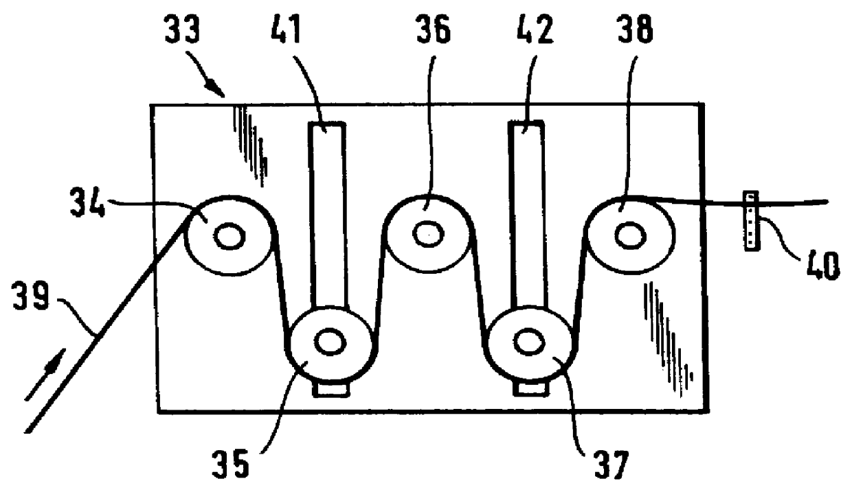
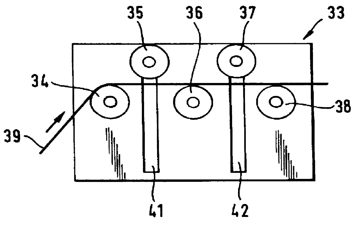
FIG. 3A shows a drawing device 33 provided with five motor-driven drums 34, 35, 36, 37 and 38 which entrain the sheet of thermoplastic filaments 39. In this device, when operating, the drums 34, 36 and 38 in the high position are arranged alternately with the drums 35 and 37 in the low position, the device 40 for detecting the sheet being in operation.

FIG. 3B shows the same device during the transfer operation.

The signal corresponding to the start of the operation, sent to the controller, has the effect of moving the drums 35 and 37 vertically along slideways 41 and 42. At the end of this vertical movement, the sheet 39 is released and only touches the upper part of the drums 34, 36 and 38. The signal corresponding to the finish of the transfer operation has the effect of returning the drums to t...

third embodiment

the device according to the invention enables the sudden variations in speed during the transfer operation to be reduced. This third embodiment is illustrated by FIGS. 4A, 4B and 4C.

FIG. 4A shows a drawing device 43 provided with two motor-driven drums 44 and 45 mounted on a turret 46. This figure shows this device in the normal drawing position. A guide roller 47 is placed upstream of the device 43 in order to increase the arc of contact of the sheet of filaments 48 with the drum 44. Downstream, the detection device 49 is operating.

FIG. 4B shows the device 43 during the transfer operation.

The signal corresponding to the start of the operation, sent to the controller, has the effect of rotating the turret 46 so as to release the sheet 48 completely. The signal corresponding to the finish of the transfer operation has the effect of rotating the turret 46 in the opposite direction so as to reestablish the drums 44 and 45 in their initial positions.

In a variant, it is possible to give ...


PUM

PropertyMeasurementUnit
compositionaaaaaaaaaa
speedaaaaaaaaaa
heightsaaaaaaaaaa

Abstract

PCT No. PCT / FR97 / 01184 Sec. 371 Date Jun. 17, 1998 Sec. 102(e) Date Jun. 17, 1998 PCT Filed Jul. 3, 1997 PCT Pub. No. WO98 / 01751 PCT Pub. Date Jan. 15, 1998The subject of the invention is a device for manufacturing a composite yarn formed by the combination of continuous glass filaments and continuous filaments of a thermoplastic organic substance, comprising, on the one hand, at least one bushing which is fed with glass, the lower face of which is provided with a multiplicity of orifices from which a multiplicity of glass filaments is drawn, and is associated with a coating device and, on the other hand, at least one extrusion head fed with a molten thermoplastic organic substance, the lower face of which is provided with a multiplicity of orifices from which a multiplicity of organic filaments is drawn, the said head being associated with a drawing device comprising at least two drums and with a venturi device which projects the organic filaments into the sheet formed by the glass filaments, and means, common to the bushing and to the extrusion head, which enable the composite yarn to be assembled and drawn, for example by a winding device such as a bobbin winder provided with spindles, in which an optical device for detecting the sheet of thermoplastic filaments running through a defined region is arranged between the drum-type drawing device and the venturi device, the said optical device being connected to a circuit which controls the speed of rotation of at least one of the drums.

Description

1. Field of the InventionThe present invention relates to a device for manufacturing a composite yarn formed by the combination of a multiplicity of continuous glass filaments and of thermoplastic organic filaments.More specifically, the invention relates to a device comprising at least one bushing fed with glass, from which is drawn a multiplicity of continuous glass filaments, and at least one extrusion head fed with a thermoplastic organic substance, from which is also drawn a multiplicity of continuous organic filaments. These organic filaments are drawn and projected by means of a venturi device into the sheet of glass filaments being drawn, all the said filaments then being gathered into the form of a composite yarn.2. Discussion of the BackgroundSuch an installation is described, for example, in Patent Application FR-A-2,698,038.In the context of the invention described in that application, the thermoplastic filaments are drawn, separately from the glass filaments, by means o...

Claims


Application Information

Patent Timeline
Patent Type & Authority Patents(United States)
IPC IPC(8): D02J1/22G01N33/36D01D5/08C03B37/02D01D5/12D02G3/18D02G3/38
CPCG01N33/365D02J1/227D02J1/22
Inventor LOUBINOUX, DOMINIQUERICHARD, DANIEL
Owner VETROTEX FRANCE S A
Why Eureka
Try Eureka