Semi-active suspension system with control circuit having a direct control loop including an inverse model of the damper

Inactive Publication Date: 2000-09-05
GEC ALSTHOM TRANSPORT SA
View PDF8 Cites 45 Cited by
  • Summary
  • Abstract
  • Description
  • Claims
  • Application Information

AI Technical Summary

Benefits of technology

An object of the invention is to provide a semi-active damper e

Problems solved by technology

From patent FR 2 660 705 it can be seen that the essential problem lies in the difficulty of achieving force servo-control with an actuator when the actuator is itself subjected to large amplitude movements at relatively low frequency, as is the case in the context

Method used


Image

  • Semi-active suspension system with control circuit having a direct control loop including an inverse model of the damper
  • Semi-active suspension system with control circuit having a direct control loop including an inverse model of the damper

Examples


Embodiment Construction

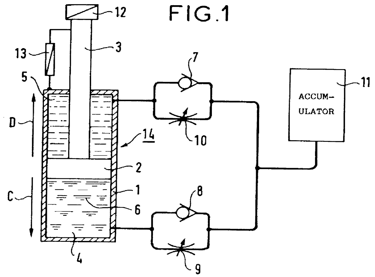
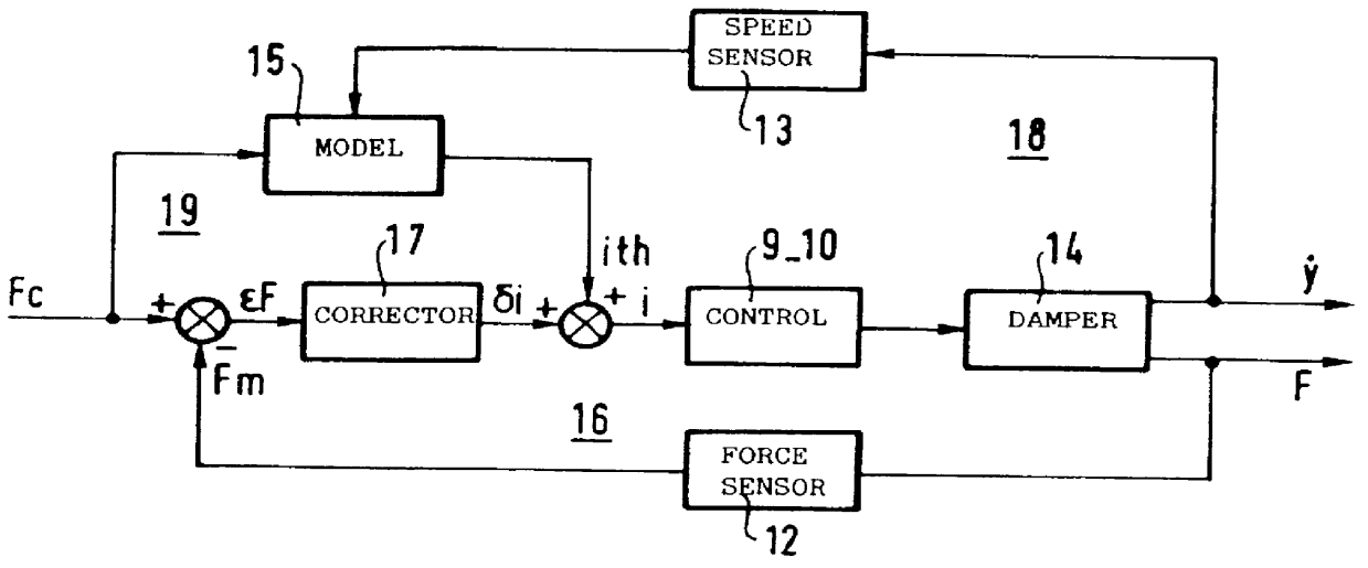
FIG. 1 is a diagram showing the principles of a controlled semi-active damper of the invention.

The controlled semi-active damper of the invention comprises a body 1 in which there slides a solid piston 2 provided with a rod 3, such that the assembly constitutes an actuator 14.

The piston 2 defines a first chamber 4 referred to as a compression chamber and a second chamber 5 referred to as an expansion chamber.

The body 2 is filled with a fluid 6, e.g. hydraulic oil.

The semi-active damper also comprises a first non-return valve 7 referred to as the compression valve, and a second non-return valve 8 referred to as the expansion valve.

First and second electrically-controlled hydraulic restriction valves 9 and 10 comprise a compression first controlled-restriction valve 9 and an expansion second controlled-restriction valve 10.

The semi-active damper also comprises a precharged oleopneumatic accumulator 11 constituted by a chamber.

Such an accumulator 11 constitutes a fixed volume containin...


PUM


Abstract

The present invention relates to a semi-active damper controlled by a control circuit including a direct control loop made up of an inverse model of the damper. The inverse model of the damper determines an ideal value for an electrical current ith for controlling a compression controlled-restriction valve and an expansion controlled-restriction valve on the basis of a measured value for a relative speed +E,dot y+EE between the two ends of the damper and on the basis of a force reference value Fc. The semi-active damper of the invention is applicable as a transverse secondary suspension for a passenger rail vehicle.

Description

The present invention relates to the relationships for controlling hydraulic dampers in general, and it relates more particularly to a semi-active damper.French patents FR 2 660 705 and FR 2 667 908 in the name of Regie Nationale des Usines Renault relate to servo-controlling the force of hydraulic actuators in a car suspension.The devices described constitute active suspensions obtained by applying control theory optimized by minimizing quadratic criteria.The term "active suspension" is used for suspensions that make use of energy generation, which energy may be hydraulic, pneumatic, or electrical, and with high levels of power being involved.In addition, a suspension is set to be "semi-active" when it possesses variable characteristics that are controlled but without significant power being supplied.A control relationship that takes account of measurements performed by sensors on a vehicle and representing movements of the vehicle make it possible to calculate the forces that the ...

Claims


Application Information

Patent Timeline
IPC IPC(8): B60G17/015B60G17/018B61F5/24F16F9/096F16F9/46F16F9/50F16F15/02
CPCB60G17/0152B60G17/018B60G17/0182B61F5/245F16F9/096F16F9/46F16F9/466B60G2202/154B60G2204/80B60G2204/82B60G2204/8304B60G2400/202B60G2400/5182B60G2400/60B60G2500/10B60G2600/18B60G2600/1873B60G17/08
Inventor BOICHOT, PHILIPPEKIRAT, REGIS
Owner GEC ALSTHOM TRANSPORT SA
Why Eureka
Try Eureka