Device having field emission type cold cathode and vacuum tank exhausting method and system in the same

a technology of cold cathode and vacuum tank, which is applied in the manufacture of electric discharge tubes/lamps, tubes with screens, separation processes, etc., and can solve the problem that the effect of residual gas on electron emission characteristics cannot be ignored in such a vacuum environment, the current fluctuation is increasing, and the emitter tip is permanent deformation or chang

Inactive Publication Date: 2000-09-05
NEC CORP
View PDF4 Cites 11 Cited by
  • Summary
  • Abstract
  • Description
  • Claims
  • Application Information

AI Technical Summary

Problems solved by technology

However, the effect of residual gas to an electron emission characteristic cannot be ignored in such a vacuum environment.
Ion impacts then bring about an increase in current fluctuation and sputtering causes the permanent deformation or changes of the emitter tips.
Consequently, great deterioration occurs in the electron emission characteristic

Method used


Image

  • Device having field emission type cold cathode and vacuum tank exhausting method and system in the same
  • Device having field emission type cold cathode and vacuum tank exhausting method and system in the same
  • Device having field emission type cold cathode and vacuum tank exhausting method and system in the same

Examples


Embodiment Construction

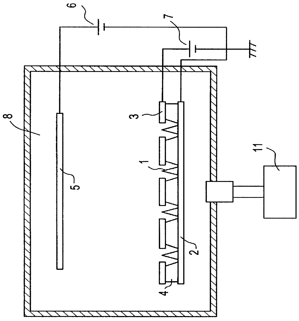
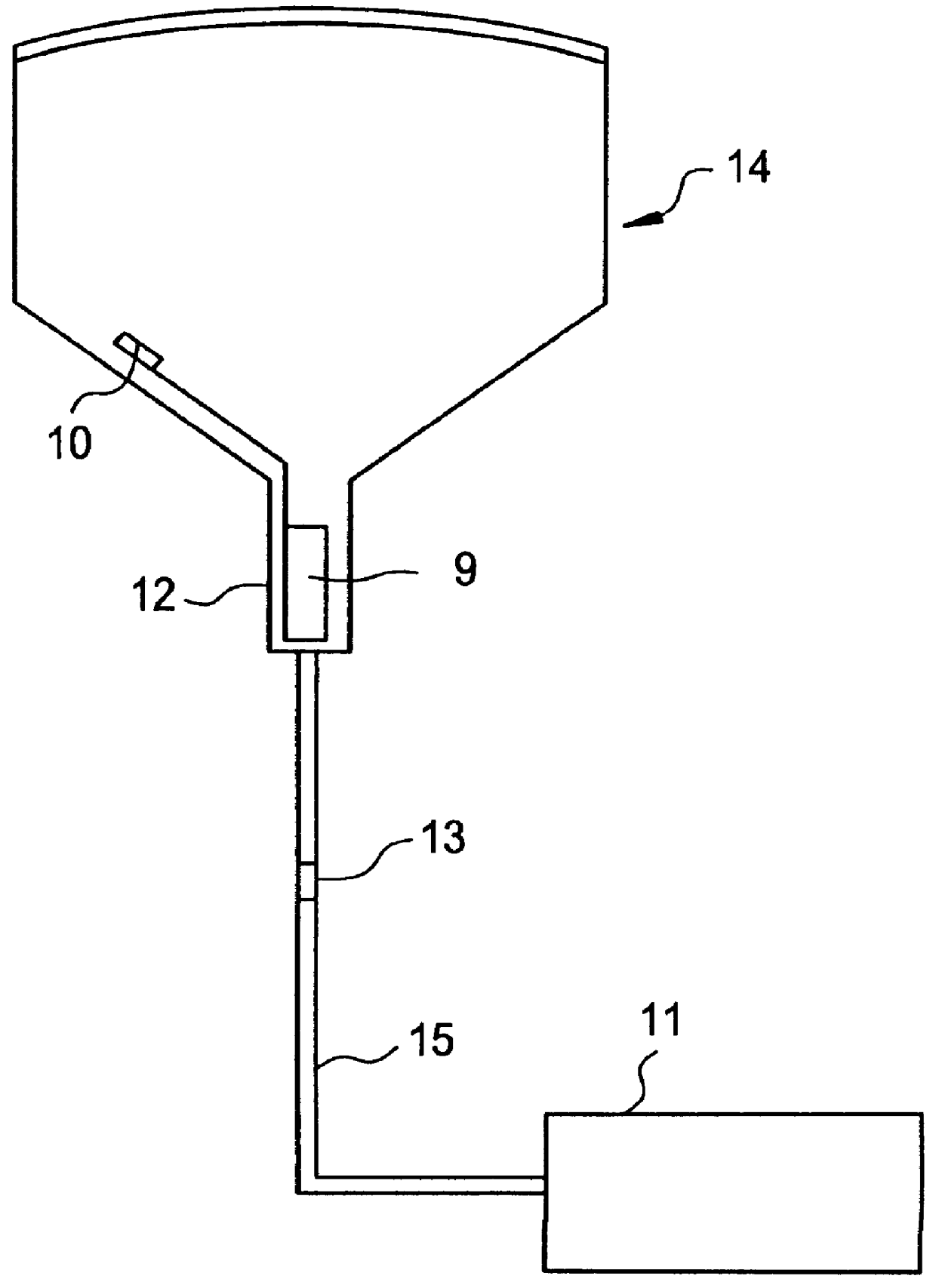
This section describes the present invention by taking as an example the use of a field emission type cold cathode as the electron gun of a CRT in an isolated vacuum tank.

According to the foregoing "Vacuum, Vol. 38" page 848, a major portion of residual gas in the CRT is Ar (argon) of 2.times.10.sup.-7 Torr, and the remaining portion contains He of 1.times.10.sup.-8 Torr and CO, N.sub.2 and CH.sub.4 of 1.times.10.sup.-8 Torr or lower. The degree of damage given by residual gas to each emitter as an electron emitting section having a sharp projection is decided by a partial pressure of the residual gas, ionization efficiency in which the residual gas is ionized by emitted electrons and a sputtering rate in which produced ions are beaten out atoms of each emitter surface.

Incident electronic energy dependence of ionization efficiency of each of various gases described in "Ionized Gasses" (Oxford University Press. 1995) by A. von Engel, is shown in FIG. 4. Each of noble gasses Ar, Kr an...


PUM


Abstract

The present invention discloses a field emission type cold cathode incorporated device, which comprises a field emission type cold cathode having a number of electron emitting sections, said sections having sharp projections, and a vacuum tank for placing the field emission type cold cathode in a vacuum environment. In this device, a partial pressure of particular noble gas in residual gas contained in the vacuum tank is set equal to or lower than C/I (C is a constant and I is a maximum emission current value per one of the number of electron emitting sections during driving of the field emission type cold cathode). Also, in order to set a partial pressure of the particular noble gas in the residual gas contained in the vacuum tank equal to C/I (C: constant) or lower, a partial pressure of the particular residual gas in the vacuum tank is monitored by a mass analyzer during vacuum tank exhaustion.

Description

1. Field of the InventionThe present invention relates to an exhausting method of a vacuum tank in a device having a field emission type cold cathode, which can be used as an electron beam source for an electron microscope, an electron beam exposing device, a cathode ray tube (CRT), a flat panel display and other various electron beam devices.2. Description of the Related ArtThe field emission type cold cathode includes an emitter formed to be a cone-shaped sharp electron emission section and a gate layer having a sub-micron level radiation hole formed to be insulated against the emitter for exposing the same, each of which is disposed in a vacuum. This cold cathode serves as an electron source for emitting electrons from the tip part of the emitter into a vacuum when a positive voltage is applied to the gate layer against the emitter. For a manufacturing technique of such a field emission type cold cathode, reference may be made to, for example, the manufacturing method of a field ...

Claims


Application Information

Patent Timeline
IPC IPC(8): H01J9/385H01J9/38H01J1/304H01J7/02H01J29/94H01J31/12
CPCH01J9/385H01J2201/304H01J2329/00
Inventor ITO, FUMINORI
Owner NEC CORP
Why Eureka
Try Eureka