Temperature compensated nuclear magnetic resonance apparatus and method

a nuclear magnetic resonance and temperature compensation technology, applied in the field of nuclear magnetic resonance, can solve the problems of reducing the size of the investigation region, increasing the temperature of the wellbore with the depth, and losing the strength of the magn

Inactive Publication Date: 2000-09-05
BAKER HUGHES INC
View PDF8 Cites 33 Cited by
  • Summary
  • Abstract
  • Description
  • Claims
  • Application Information

AI Technical Summary

Problems solved by technology

However, the wellbore temperature increases with the depth.
As the temperature increases, the permanent magnets lose strength, which reduces the size of the region of investigation and also moves it closer to t

Method used


Image

  • Temperature compensated nuclear magnetic resonance apparatus and method
  • Temperature compensated nuclear magnetic resonance apparatus and method
  • Temperature compensated nuclear magnetic resonance apparatus and method

Examples


Embodiment Construction

)

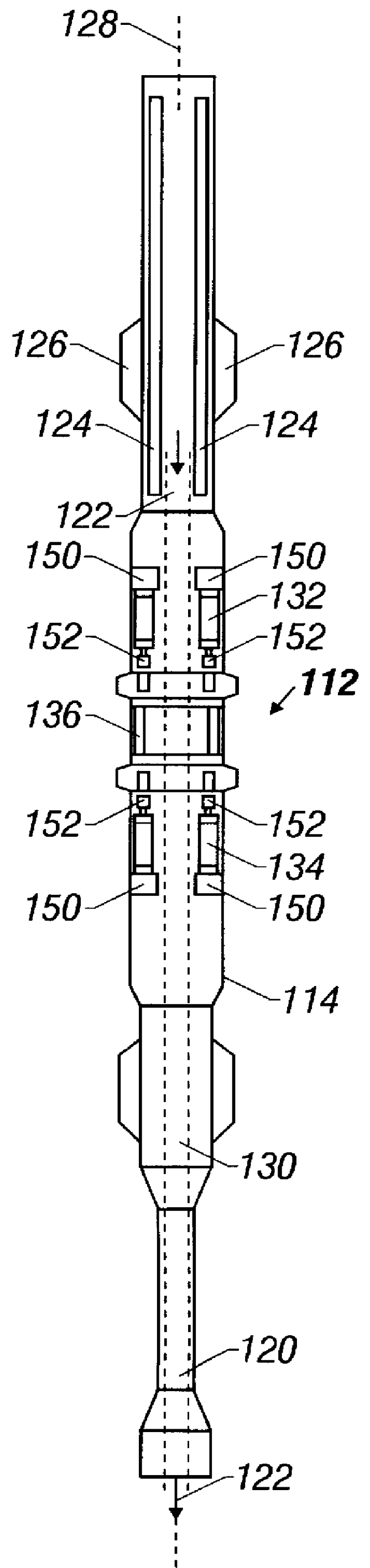
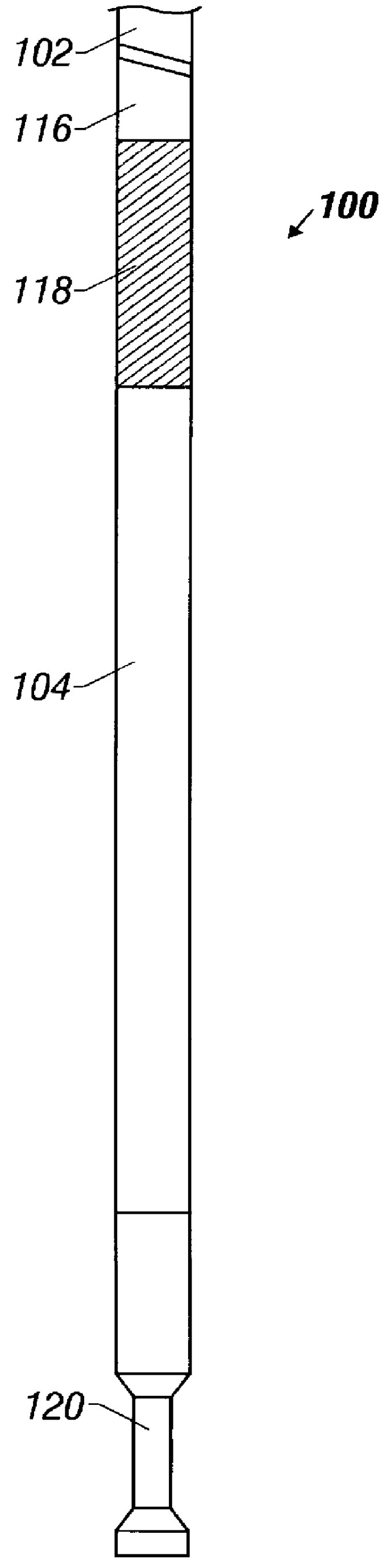
Referring to FIGS. 1A-1C, a drilling assembly 100 at the end of a drill string 102 or coiled tubing is illustrated according to the present invention. A measurement-while-drilling (MWD) tool 104, an associated pulsed nuclear magnetic resonance (NMR) tool 112 (contained within a housing 114) and electronic circuitry 124, and a pulsed power unit 118 are connected in tandem in the drilling assembly 100. Flex subs 120 are used for example in connecting the MWD tool 104 and the NMR tool 112 in the drilling assembly 100. The MWD tool 104 may also include a sonic sensor, a density measurement tool, and a porosity measurement tool. A communication sub 116 using, for example, two-way telemetry, is also provided as illustrated in the drilling assembly 100.

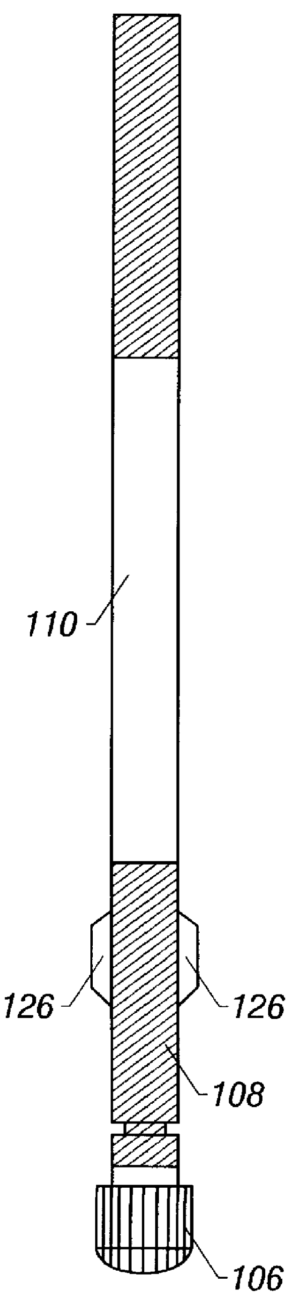
The drilling assembly 100 includes a drill bit 106, bearing assembly 108, and downhole mud motor 110. The drill string 102 includes, for example, sections of drill pipe connected end-to-end or a generally continuous coiled tubing (as descri...


PUM


Abstract

A method and apparatus for determining a characteristic of an earth formation surrounding a borehole in which a pulsed nuclear magnetic resonance (NMR) tool is received. A static magnetic field is produced in the borehole using at least two spaced-apart magnets in the NMR tool. The static magnetic field has a first region of substantially uniform magnetic intensity at a first location in the borehole, the first location in the borehole having a first temperature. The NMR tool is moved to a second location in the borehole having a second temperature, and a static magnetic field having a second region of substantially uniform magnetic is produced. The at least two spaced-apart magnets are controllably moved relative to each other wherein the first region of substantially uniform magnetic intensity and the second region of substantially uniform magnetic intensity are substantially equal in size and distance from the NMR tool.

Description

1. Field of the InventionThis invention relates to nuclear magnetic resonance and more particularly to a temperature compensated nuclear magnetic resonance apparatus and method.2. Description of the Related ArtTo obtain hydrocarbons such as oil and gas, a drilling assembly (also referred to as the "bottom hole assembly" or the "BHA") carrying a drill bit at its bottom end is conveyed into the wellbore or borehole. The drilling assembly is usually conveyed into the wellbore by a coiled-tubing or a drill pipe. In the case of the coiled-tubing, the drill bit is rotated by a drilling motor or "mud motor" which provides rotational force when a drilling fluid is pumped from the surface into the coiled-tubing. In the case of the drill pipe, it is rotated by a power source (usually an electric motor) at the surface, which rotates the drill pipe and thus the drill bit.Bottom hole assemblies generally include several formation evaluation sensors for determining various parameters of the forma...

Claims


Application Information

Patent Timeline
IPC IPC(8): G01V3/32G01V3/18
CPCG01V3/32
Inventor KRUSPE, THOMASSLADE, ROBERT A.
Owner BAKER HUGHES INC
Why Eureka
Try Eureka