Antenna switching circuits for radio telephones

a switching circuit and radio telephone technology, applied in the direction of waveguide type devices, antenna supports/mountings, radio transmission for post communication, etc., can solve the problems of difficult operation of the antenna bandwidth, use of mechanical switches, and achieve slow switching time and large and bulky components

Inactive Publication Date: 2000-09-05
NOKIA MOBILE PHONES LTD
View PDF12 Cites 159 Cited by
  • Summary
  • Abstract
  • Description
  • Claims
  • Application Information

AI Technical Summary

Benefits of technology

Also disclosed is an antenna switching arrangement for a dual band phone that eliminates a requirement for duplexers, while enabling

Problems solved by technology

In a dual band mobile phone the operational bandwidth of the antenna presents a difficult problem.
However, due to the large difference in operational frequencies conventional dual band mobile phones typically provide a separate receiver front end and a separate transmitter power amplifier section for each band.
However, this approach has at least two significant disadvantages.
First, the use of a mechanical switch has the disadvantage of requiring a large and bulky component with a slow switching time.
However, the use of an electronic switch is disadvantageous in that it introduces a significant insertion loss into the RF path.
This insertion loss must be compensated for by usi

Method used


Image

  • Antenna switching circuits for radio telephones
  • Antenna switching circuits for radio telephones
  • Antenna switching circuits for radio telephones

Examples


Embodiment Construction

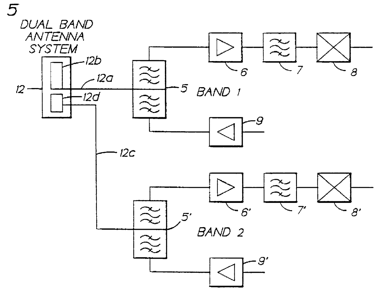
FIG. 5 illustrates a first embodiment of this invention that eliminates the antenna switch of FIG. 3 through the use of a single, dual band antenna 12. In the embodiment of FIG. 5 there are two feedlines, preferably each having an impedance of 50 ohms. A first feedline 12a connects the Band 1 (e.g., 800 MHz analog) duplexer 5 to a first element 12b of the dual band antenna 12. A second feedline 12c connects the Band 2 (e.g., 1.9 GHz TDMA) duplexer 5' to a second element 12d of the dual band antenna 12. The elements 12b and 12d are each electrically optimized for operation in their respective bands, and may be disposed on a common antenna substrate or core and separated by a suitable dielectric material. The antenna elements 12b and 12d are so implemented that the electrical isolation between them is sufficiently high to prevent loading between the antenna ports of the dual band RF sections.

This embodiment eliminates the insertion loss due to the use of band or antenna switches, and ...


PUM


Abstract

Disclosed are various embodiments of circuitry for coupling first and second transceivers of a dual band radio telephone to integral and external antennas. The circuitry uses impedance matching lengths of transmission lines and switches arranged to provide a minimum insertion loss. Also disclosed is an embodiment for use with a single band radio telephone, such as a digital TDMA radio telephone that either transmits or receives at any given time. Also disclosed is an antenna switching arrangement for a dual band phone that eliminates a requirement for duplexers.

Description

FIELD OF THE INVENTIONThis invention relates generally to methods and apparatus for connecting radio frequency (RF) circuits to one or more antennas and, in particular, to circuits used in single and dual band radio telephones, such as cellular telephones.BACKGROUND OF THE INVENTIONIn a dual band mobile phone the operational bandwidth of the antenna presents a difficult problem. By example, such a mobile phone may need to be operable in the 800 MHz band (e.g., analog AMPS) at one time, and then in the 1.9 GHz band (e.g., digital PCN) at another time. Preferably, a single antenna is used for both bands. However, due to the large difference in operational frequencies conventional dual band mobile phones typically provide a separate receiver front end and a separate transmitter power amplifier section for each band.FIG. 1 illustrates one such conventional construction for a dual band mobile phone. A single antenna system 1 is connected to a Band 1 receiver front end and transmitter pow...

Claims


Application Information

Patent Timeline
IPC IPC(8): H01Q5/00H01Q1/24H01Q21/30H04B1/48H04B1/44H04B1/40H04B1/52H04B1/50H01P1/10H01P1/15H04B1/403H04B7/26
CPCH01Q1/24H01Q1/242H01Q21/30H04B1/005H04B1/406H04B1/48H04B1/52
Inventor MATERO, JORMAKANGAS, MATTI I
Owner NOKIA MOBILE PHONES LTD
Why Eureka
Try Eureka