Parallel filters for plastic melts

a filter and plastic melt technology, applied in the direction of filtering element filters, filtration separation, separation processes, etc., can solve the problems of insufficient space around the inlet and outlet of the filter housing, inability to avoid mechanical damage during cleaning and maintenance work, and lack of accessibility, so as to achieve easy work, reduce space, and achieve quick and thorough

Inactive Publication Date: 2000-09-12
LINDAUER DORNIER GMBH
View PDF7 Cites 8 Cited by
  • Summary
  • Abstract
  • Description
  • Claims
  • Application Information

AI Technical Summary

Benefits of technology

By tilting a filter housing about its hinging axis, for example by an angle of 90.degree., the inlet and outlet sealing surfaces of the respective melt valves and of the filter cartridge become easily accessible without requiring substantial space in the vicinity of the filtering system compared to conventional systems in which the filter housings must be displaced linearly away from the valves, for the cartridge exchange. Where a linear displacement is required in conventional systems, the spacing between the operating position and the maintenance position of the filter housing must be such that an operator can step into that space while at the same time being able to use the required tools such as cleaning brushes having handles of substantial length sufficient to clean the interior of the filter housings.
The tilting of one filter housing or of one or the other filter housing about a journal axis or hinge axis requires very little space because the sealing surfaces that need to be cleaned are positioned substantially at a right angle relative to each other, thereby facilitating an easy work that can be done with free access to the respective filter housing with its sealing surfaces. This free access for the work to be performed has the advantage that the work itself can be done quicker and more thoroughly while simultaneously providing the maintenance personnel with an advantageous working position and respective working conditions. The available space makes the work safer and less tiring. Injuries due to contact with sharp edges or due to thermal influences are avoided. The maintenance personnel can assume the most convenient position during working so that long term adverse influences or damages are avoided. Moreover, these convenient working conditions reduce the errors made by the maintenance personnel particularly with regard to contamination particles and / or mechanical damage to the melt contacting surfaces of the components especially the sealing elements are avoided since these convenient working conditions permit maintaining concentrated attention by the maintenance personnel for longer periods of time than was possible heretofore.
Furthermore, the following features reduce the operating costs of the present filter systems. The compact construction which permits short travel distances for the melt from the extruder to the filter system, requires few melt detours. Easily exchangeable filter cartridges and exchangeable sealing elements may be used. All couplings may be accomplished by so-called quick couplings, clamping couplings, and screwed connections. Moreover, the compact construction with short distances to be travelled by the melt keeps the production of reject film sections low. Incidentally, the short flow distances for the melt are assured by connecting the filters to the valves and the valves to the melt extruder through short substantially straight pipes. Further, only a few melt contacting surfaces and sealing surfaces need to be cleaned so that the danger of contaminating particles entering the system is reduced. Similarly, the cleaning operation is easily performed so that extrudate remainders or other contaminating particles conventionally caused by mechanical damage to the surfaces to be cleaned, are substantially avoided and thus do not enter into the next operating cycle of a cleaned filter section.

Problems solved by technology

It is a disadvantage of conventional filter devices for extruders that the space available around the inlets and outlets of the filter housings, is rather inadequate for the above mentioned cleaning operations.
This lack of accessibility is aggravated by the fact that the operating temperature of the extrudate is about 800.degree. C. which requires a special dexterity of the maintenance personnel which must work under adverse conditions due to high heat radiation.
Avoiding such mechanical damage during cleaning and maintenance work is difficult under the above mentioned working conditions.
Further, not properly cleaned melt channels can contaminate the extrudate when the filter is restarted after a cleaning operation.
Such contamination of the melt in turn results in a faulty film product that can lead to tearing of the extruded film and the like.
However, a substantial structural volume with pipelines and three-way valves requires a correspondingly substantial space.
This requirement calls for an additional space and entails higher manufacturing, assembly and maintenance costs.
The pipeline assembly for connecting the two three-way valves with the two filters entail unavoidable detouring of the extrusion melt, since the melt does not flow along a straight conduit.
Hence, the feeding or transportation of the melt requires additional costs as far as energy consumption by the conveying pump and heating of the system are concerned.
During the cleaning operation the operating personnel is exposed to substantial thermal effects because the operator must perform his job by standing between the displaced hot filter housing and the remaining hot sections of the system.
In addition to high manufacturing and construction or assembly costs, the operating costs are also contributing to a substantial disadvantage.
A total of six melt detours in the piping system further contributes to the increased costs especially in terms of a higher power consumption.
However, maintenance and cleaning operations are aggravated because of the limited space available in the inlet and outlet area of the conventional filter system according to the Swiss Patent and due to the fact that a high radiation heat from the filter housing that is in a working position aggravates the working conditions.
Thus, a proper maintenance and thorough cleaning operation is only possible when the melt flow is completely interrupted and the filter mounting body is tilted or shifted into the maintenance position with both filter housings.

Method used


Image

  • Parallel filters for plastic melts

Examples


Embodiment Construction

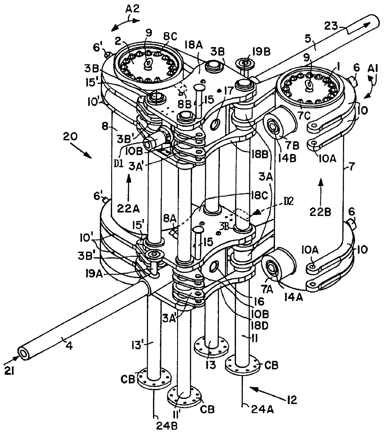
The single FIGURE shows a double filter, however, the construction of a single filter is substantially the same, except that either the left-hand or right-hand filter housing with its mounting elements is omitted.

The FIGURE shows filter system 20 with a first filter cartridge 1 removably mounted in a first filter housing 7. Screws 7C hold the filter cartridge 1 in the first housing 7. When the screws 7C are released, the filter cartridge 1 can be lifted out of the housing 7 by a lifting mechanism not shown. The lifting mechanism engages, for example, an eye bolt 9. Similarly, a second filter cartridge 2 is mounted in a second filter housing 8, whereby screws 8C and the eye bolt 9 serve for the same purposes just described. As shown in the drawing FIGURE, the filter housing 7, 8 each include a peripheral wall that completely surrounds a respective axis. The first filter housing 7 is shown in a service position tilted counterclockwise out of a working or filtering position as indicate...


PUM

PropertyMeasurementUnit
operating temperatureaaaaaaaaaa
angleaaaaaaaaaa
rotation angleaaaaaaaaaa

Abstract

A filter for filtering plastic melt prior to feeding the melt into an extruder nozzle, for example a thermoplastic film extruder nozzle, has preferably two filter housings for holding respective exchangeable filter cartridges. Both filter housings are articulated by hinges to a column mounting so that one filter housing can be serviced while the other filter housing with its filter cartridge is in a filtering position and vice versa. A single filter may be used alternatively. In both instances the column mounting may include at least one, preferably two, mounting columns.

Description

The invention relates to large surface area filters for plastic melts, particularly thermoplastic melts that are supplied from an extruder into a melt filter for producing plastic films. The filter may be a single filter or a double filter.BACKGROUND INFORMATIONSingle melt filters are used on the one hand where a continuous film production is not possible or not necessary so that an interruption of the production due to changing of filter cartridge or other maintenance work is acceptable. Such single melt filters are also used in a second filtering stage with a fine filtering cartridge downstream of a double melt filter system. Customarily the double melt filter is positioned between a melt pump and a film laminating extruder or a melt pump and a melt film extruder. The single melt filter is positioned downstream of the melt pump as close as possible to the extrusion nozzle. Downstream of the extrusion nozzle normally a cooling roller is arranged which cools the extrudate to form th...

Claims


Application Information

Patent Timeline
Patent Type & Authority Patents(United States)
IPC IPC(8): B29C47/08B29C47/68B29C47/58B01D35/12B29C48/694
CPCB29C47/0822B29C47/681B29C47/0021B29C48/08B29C48/2562B29C48/694B29C48/6914
Inventor RUTZ, ANDREASMUELLER, FRIEDRICH
Owner LINDAUER DORNIER GMBH
Why Eureka
Try Eureka