Method for measuring the flow of fluids

a technology for measuring the flow of fluids and fluids, applied in the direction of liquid/fluent solid measurement, instruments, devices using optical means, etc., can solve the problems of amplifying the measurement error, particle accuracy not faithfully following the fluid flow on-going, and inevitably sacrifice the accuracy of flow measuremen

Inactive Publication Date: 2000-09-12
OSAKA GAS CO LTD
View PDF7 Cites 15 Cited by
  • Summary
  • Abstract
  • Description
  • Claims
  • Application Information

AI Technical Summary

Benefits of technology

[The mean effective data rate was determined with Dantec's burst signal analyzer. When the symmetry of scatter signals is disturbed, the peak frequency value after Fourier transformation is depressed. Therefore, only the signals with a frequency peak/reference frequency peak ratio over a given value were regarded as valid data. In other words, the dat...

Problems solved by technology

However, as apparent from these microphotographs, the conventional tracer particles have the following drawbacks, 1) through 5), which amplify the measurement error.
3) Because the apparent specific gravity of the particulate tracer differs markedly fro...

Method used


Image

  • Method for measuring the flow of fluids
  • Method for measuring the flow of fluids
  • Method for measuring the flow of fluids

Examples


example 1

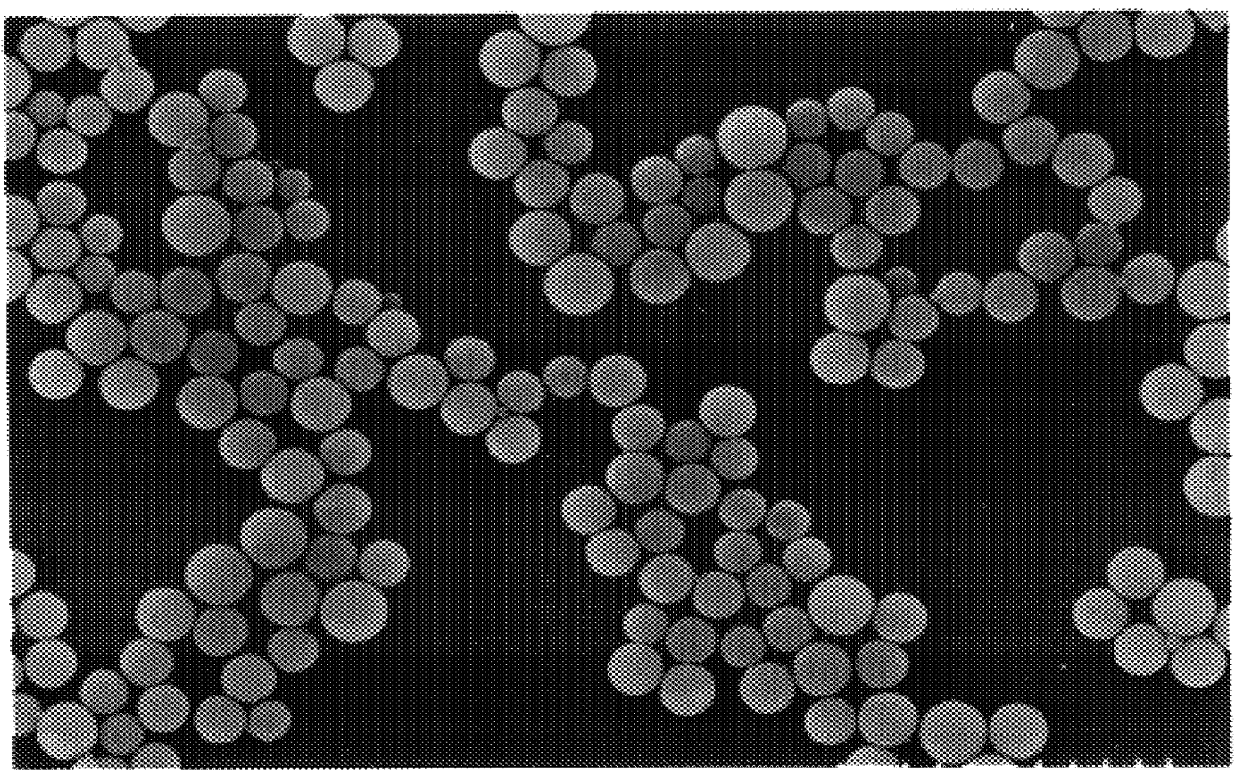
Using a hollow spherical particulate SiO.sub.2 tracer with 70% of individual particles having diameters within the range of mean particle diameter=1.5 .mu.m.+-.0.4 .mu.m, the shell thickness of which is one-fifth of the diameter of the particle, the velocity of air within a cylinder was measured using a laser velocimeter under the following conditions and the relationship between the sample data rate and the mean effective data rate was investigated. Thus, for increasing the number of data per unit time (sample data rate) stepwise, the flow rate was increased stepwise (with the concentration of tracer particles kept constant) to increase the quantity of particles passing through the inference figure at the flowmeter. Of the resulting data, the percentage of data useful for velocity assessment (effective data rate) was determined. (Mean flow rate =ca. 20 m / min.)

1. Instrument: Fiber type laser Doppler velocimeter (FLDV)

(cf. Ikeda, Y., Hikosaka, M., Ohira, T., and Nakajima, T., Scaveng...

example 2

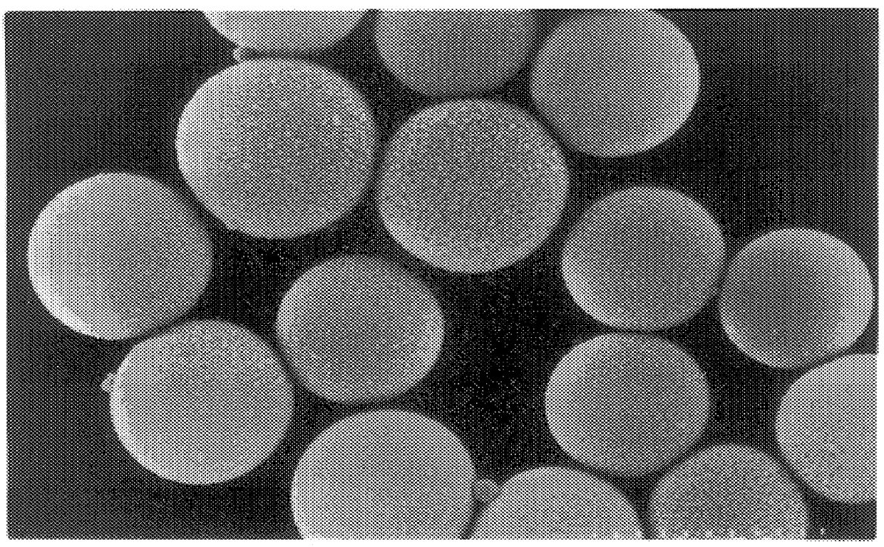
The same measurement as Example 1 was performed using a hollow spherical particulate SiO.sub.2 tracer with 90% of individual particles having diameters within the range of 1 to 5 .mu.m (the shell thickness was one-fifth of the diameter of the particle). The results are shown in Table 2.

It will be seen from Table 2 that although the mean effective data rates are not as high as those obtained in Example 1 because of the broader tracer particle size distribution, there are obtained stable effective data rates even at high sample data rates.

production example 1

The following example is intended to illustrate the production of tracer particles by the reversed micelle method.

A 10 .mu.m-thick polyimide film was irradiated with a KrF excimer laser (wavelength 251 nm) to provide perforations sized 2.0 .mu.m. This perforated polymer film was mounted in an emulsification device illustrated in FIG. 17 and an aqueous solution of the tracer precursor substance was fed under pressure into an organic solution with a syringe pump. The feeding rate was 1 g / cm.sup.2 and the temperature was 25.degree. C.

The construction of the device shown in FIG. 17 is summarized below. The reference numeral 10 indicates a volumetric syringe pump 10. The polymer membrane, indicated by 12, is mounted in the forward portion of the volumetric syringe pump. The reference numeral 14 indicates a screen for supporting said polymer membrane. Indicated by the numeral 16 is a cylindrical reactor which is communicating with said syringe pump 10. The reference numeral 20 indicates a...


PUM


Abstract

The disclosed method of measuring the flow of a fluid with a porous particulate ceramic tracer and an optical instrument is characterized in that spherical particles having diameters in the range of 0.5 to 150 mu m are used as the tracer. Inasmuch as the tracer particles for flow measurement are spherical, the sectional area of scattered light to be detected by an optical sensor means is constant regardless of the orientation of particles. Furthermore, spherical particles have no surface irregularities that might cause concatenation so that individual particles are not agglomerated in tracking a fluid flow, thus contributing to improved measurement accuracy.

Description

The present invention relates to a method for measuring the flow of fluids, herein after referred to as "flow measurement". It should, however, be understood that the term "flow measurement" as used throughout this specification means not only a measurement of the flow velocity of a gas, such as air, fuel gas, etc., or a liquid, such as water, liquefied gas, etc., but also a topological visualization of the distribution of such gas or liquid.Prior ArtThe particles heretofore used as tracer particles in optical flow measurements are porous particles made of SiO.sub.2, TiO.sub.2, SiC or the like which are obtainable by a coprecipitation process or from a natural material such as the mineral ore. These particles generally have a mean particle diameter of about 0.5 to 150 .mu.m.In a measurement of the flow velocity using a laser device such as a laser Doppler velocimeter, a phase Doppler velocimeter or the like, tracer particles somewhere between 0.5 and 10 .mu.m in mean diameter, in pa...

Claims


Application Information

Patent Timeline
IPC IPC(8): G01F1/704G01F1/708G01P5/26G01P5/00G01F1/7086G01F3/00G01P3/36G01P5/20
CPCG01F1/661G01F1/704G01F1/7086G01P5/001G01P5/005G01P5/20G01P5/26G01F3/00
Inventor IPPONMATSU, MASAMICHINISHIGAKI, MASASHIHIRANO, AKIRANAKAJIMA, TSUYOSHIIKEDA, YUJISUZUKI, MINORUTSURUTANI, TSUYOSHI
Owner OSAKA GAS CO LTD
Why Eureka
Try Eureka