Key operated rotary switch for disabling an automobile air bag supplemental restraint system

a technology of supplemental restraint system and rotary switch, which is applied in the direction of vehicular safety arrangement, pedestrian/occupant safety arrangement, transportation and packaging, etc., can solve the problems of severe impact injuries to passengers, limited situations, and airbags themselves posing potential safety hazards

Inactive Publication Date: 2000-09-26
METHODE ELETRONICS INC
View PDF17 Cites 14 Cited by
  • Summary
  • Abstract
  • Description
  • Claims
  • Application Information

AI Technical Summary

Problems solved by technology

While airbags have been very successful in preventing injuries and death, it has also been found that under certain conditions the airbags themselves may pose a potential safety hazard due to the explosive force with which they are deployed.
Generally these situations are limited to those where the driver and / or the front seat passenger are relatively small in physical stature, or when small children are placed in the front seat of the vehicle.
In these cases, the explosive force of the airbag deployment is sufficient to cause severe impact injuries to the passenger which the airbag unit is putatively designed to protect.
A manually operated switch may provide such an interface, however, the addition of such a switch raises a number of safety concerns which must be considered before such a switch may be safely integrated into the airbag system.
A first issue raised by adding a disabling switch to the airbag system is how to limit access to the switch itself.
However, adding a key switch to the passenger compartment of an automobile raises further safety issues which must also be addressed in designing a safe and effective airbag disarm switch.
A significant drawback to locating key operated switches within the passenger compartment of an automobile is that the key, when left within the switch mechanism, represents a potential source of injury to occupants of the car in the event of a collision.
The sharp narrow contours of a key extending from the switch housing can cause severe puncture wounds to a human body impacting the key due to the force of the collision.
Generally, a key protruding from a dash mounted airbag disarm switch is unlikely to meet this standard.
A second problem with employing a key switch to arm and disarm an airbag, is that most standard rotary type switches can be manipulated into an ambiguous middle position between valid switch states.
If this were to occur in an airbag disable switch, the operator of the vehicle could not be certain how the airbag system would deploy in the event of a collision.
It is possible that airbags could deploy when they were not supposed to, or fail to deploy when it was desired that they should.
In either case, the result could mean catastrophic injury to the occupants of the vehicle.
Thus, the key may tot be inadvertently left in the switch mechanism where it may pose a risk of injury to the occupants of the vehicle.

Method used


Image

  • Key operated rotary switch for disabling an automobile air bag supplemental restraint system
  • Key operated rotary switch for disabling an automobile air bag supplemental restraint system
  • Key operated rotary switch for disabling an automobile air bag supplemental restraint system

Examples


Embodiment Construction

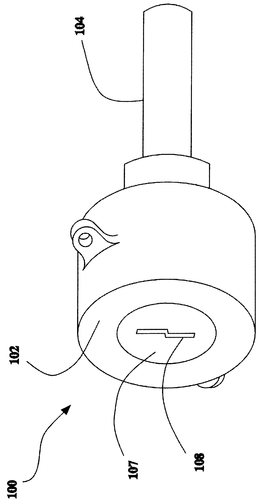
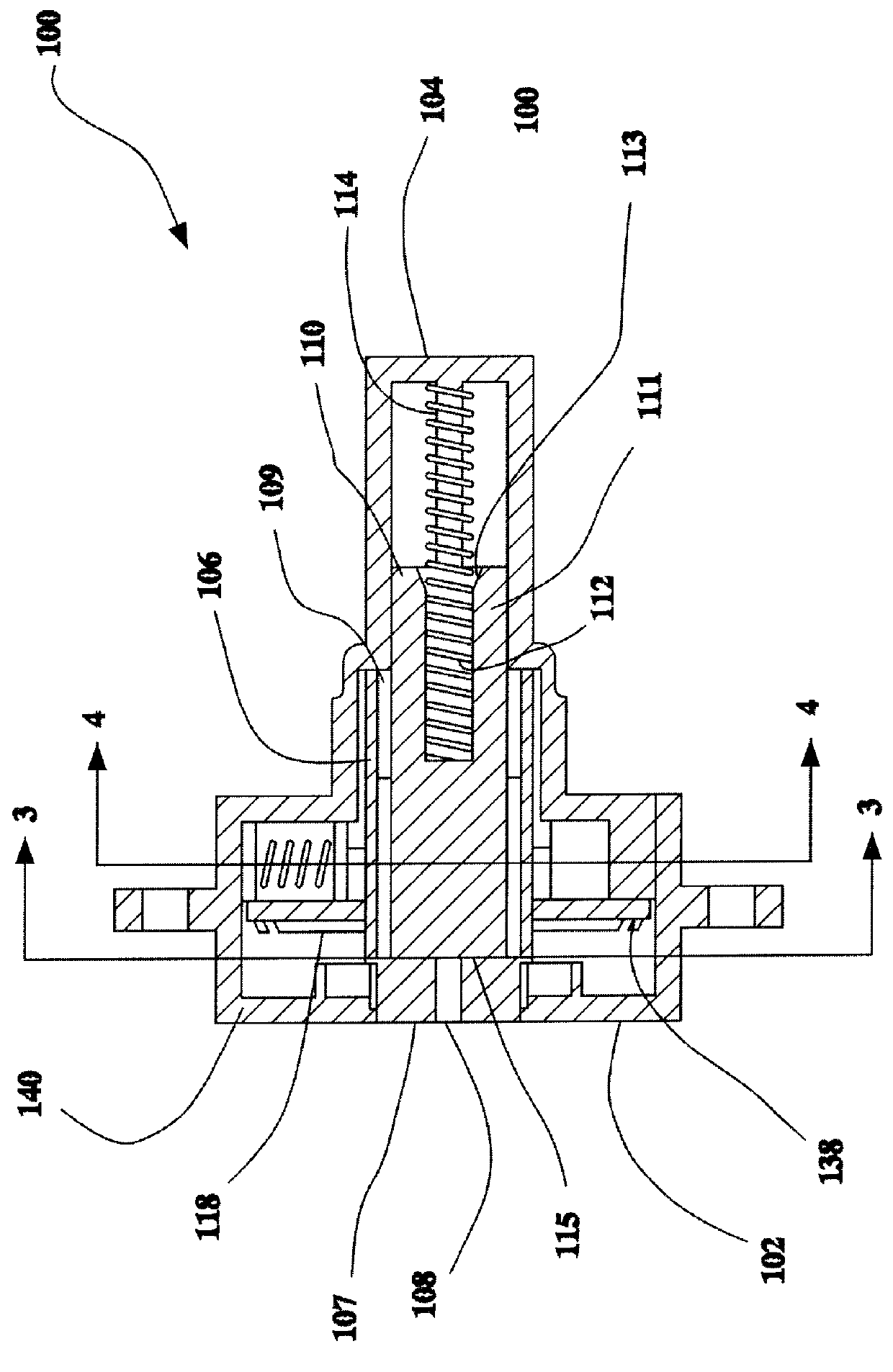
Referring to FIGS. 1 and 2 a key operated rotary switch is shown 100. The key operated switch includes a two piece housing including a cover 102 and a base 104. Contained within the housing is a cylindrical rotor 106. A transverse front end-of the rotor 107 includes a key receiving slot 108 centered about the rotational axis of the rotor. The rotor 106 is essentially a hollow cylinder having an open base 109. A separate cylindrical plunger 110 is mounted within the rotor 106. As with the rotor, the plunger 110 is also configured as a hollow cylinder. A rear end 111 of plunger 110 forms a hollow central bore 113 for accommodating a coiled compression spring 112. The coil spring 112 is disposed within the hollow central bore 113, between the plunger 110 and the base of the housing 104. A guide post 114 extends internally from the base 104 to support the lower portion of the spring 12. The coil spring loads the plunger such that a flat upper surface of the plunger 115 is biased against...


PUM


Abstract

A key operated switch is provided for disabling an automobile air bag passive restraint system. The two or four position switch includes a housing, a rotor, a plurality of rotationally actuated electrical switch elements, a key ejecting mechanism, and a positive positioning detent. The switch assembly is arranged such that a transverse surface of the rotor defining a key slot is accessible through the housing. The key slot allows an operating key to be manually inserted into the rotor. In or order to insert the key, however, the therein, a certain minimum amount of force must be applied to the key sufficient to overcome the key ejecting mechanism. In the absence of such minimum insertion force, the key ejecting mechanism will act expel the key from the rotor. Once inserted into the rotor, the key may be manually rotated which causes corresponding rotation of the rotor. The rotation of the rotor in turn, actuates select electrical switch elements attached to the rotor, according to the angular position of the rotor. The electrical switch elements define a plurality of distinct switch states, each corresponding to a particular angular position of the rotor. Finally, the positive positioning detent forces the rotor to an angular position corresponding one of the distinct switch states defined by the electrical switch elements during those periods when no external torque is being applied to the rotor.

Description

1. Field of the InventionThe present invention relates to a key operated rotary switch particularly adapted for enabling and disabling an automobile air bag supplemental restraint system.2. Discussion of the BackgroundAirbag supplemental restraint systems have been widely used to protect automobile occupants in the event of a front impact collision. Typically an airbag unit will be located in an automobile's steering wheel and another will be located in the dashboard opposite the front passenger seat. During a crash, impact sensors located in the car's bumper will sense the onset of the collision and send an electrical signal to the airbags. The electrical signals ignite small explosive charges within each airbag unit, and the ensuing controlled explosions generate large amounts of expanding gases which rapidly inflate the airbags, thereby forming a gaseous cushion to protect the driver and / or a passenger riding in the front of the car.While airbags have been very successful in prev...

Claims


Application Information

Patent Timeline
Patent Type & Authority Patents(United States)
IPC IPC(8): H01H27/06H01H27/00H01H19/11H01H19/00B60R21/01H01H19/58E05B65/12B60R21/015B60R21/16E05B17/22
CPCH01H19/11H01H27/06B60R21/01564H01H19/585Y10S70/30Y10T70/7763
Inventor CHANDRA, KANNANKAUFMAN, DENNISLARSEN, JAMESRAMAMURTHY, RAJKUMAR
Owner METHODE ELETRONICS INC
Why Eureka
Try Eureka