Method and apparatus for wireless powering and recharging

Inactive Publication Date: 2000-10-03
RAYTHEON BBN TECH CORP
View PDF11 Cites 852 Cited by
  • Summary
  • Abstract
  • Description
  • Claims
  • Application Information

AI Technical Summary

Problems solved by technology

Photoelectric cells may not provide adequate power under low light conditions.
Moreover, situations may arise where a large number of batteries has to be charged simultaneously and/

Method used


Image

  • Method and apparatus for wireless powering and recharging
  • Method and apparatus for wireless powering and recharging
  • Method and apparatus for wireless powering and recharging

Examples


Embodiment Construction

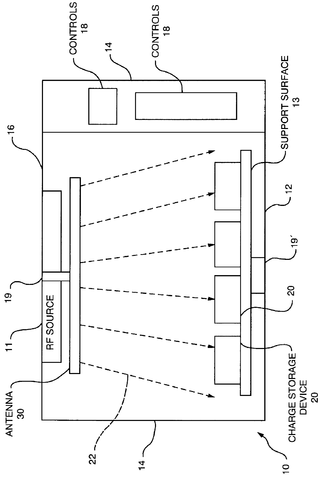
Referring to FIG. 1, a housing 10 includes an RF source 11, e.g., an oscillator circuit coupled to a power amplifier or a magnetron, generating RF power. The RF power is coupled to an antenna 30 which radiates the RF power, preferably unidirectionally, towards a bottom portion 12 of the housing 10. In the illustrated example, the antenna 30 is supported from a top housing portion 16, but may also be located on a side wall 14 of the housing 10 (not shown) and may be adapted to rotate about a vertical axis 19 to distribute the typically linearly polarized RF radiation uniformly in the horizontal plane of the bottom portion 12. The operation of the RF source 11, e.g., the duty cycle and the operating time, can be controlled via controls 18 located on an operating panel which may be disposed on the housing, as seen in FIG. 1, or implemented by remote control (not shown).

A number of charge storage devices 20, e.g. rechargeable batteries and / or devices, are placed on a support surface 13 ...


PUM


Abstract

An arrangement is provided for charging a charge storage device by placing the charge storage device in an RF or microwave radiation field. One or more antennas which receive the radiated RF electromagnetic field are placed on the charge storage device. Rectifiers connected to the antennas rectify the received RF electromagnetic field an produce a DC output current which is used to charge the charge storage device. The charge storage device may be a battery or a capacitor and may form an integral part of an electronic device. The same RF field that charges the charge storage device can also be employed to communicate data to transponders which may be associated with computing devices.

Description

1. Field of the InventionThis application relates to the field of providing an electrical charge to a charge storage device and more particularly to the field of contactless charging of batteries using RF radiation.2. Description of Related ArtElectronic devices, in particular electronic devices used for wireless communication, are typically powered by rechargeable batteries, capacitors or photoelectric cells. Photoelectric cells may not provide adequate power under low light conditions. Rechargeable batteries and capacitors and devices with built-in batteries, all of which will subsequently be referred to as batteries, have to recharged periodically, which is typically done by placing the battery in a charger to establish a path for the electric charging current between the battery and the charger.It is also known to charge batteries by electromagnetic induction. In this case, the battery includes a pick-up coil which is placed in close proximity to an electromagnetic transmitting ...

Claims


Application Information

Patent Timeline
IPC IPC(8): G06K19/07H02J7/02
CPCG06K19/0701H02J7/025G06K19/0723H02J7/0044H02J50/402H02J50/005H02J50/20H02J50/70H02J50/23H02J50/27H02J50/80
Inventor KRISHNAN, RAJESH
Owner RAYTHEON BBN TECH CORP
Why Eureka
Try Eureka