Transmission for motor vehicle

Inactive Publication Date: 2000-10-10
SCHAEFFLER TECH AG & CO KG
View PDF10 Cites 28 Cited by
  • Summary
  • Abstract
  • Description
  • Claims
  • Application Information

AI Technical Summary

Benefits of technology

Another object of the invention is to provide a novel and improved method of reducing or eliminating leakage of a fluid which can or which must be conveyed at an elevated pressure along a path defined by parts that are movable relative to each other.
A further object of the inventio

Problems solved by technology

A drawback of such connections for the end portions of the conduit is that the uni

Method used


Image

  • Transmission for motor vehicle
  • Transmission for motor vehicle
  • Transmission for motor vehicle

Examples


Embodiment Construction

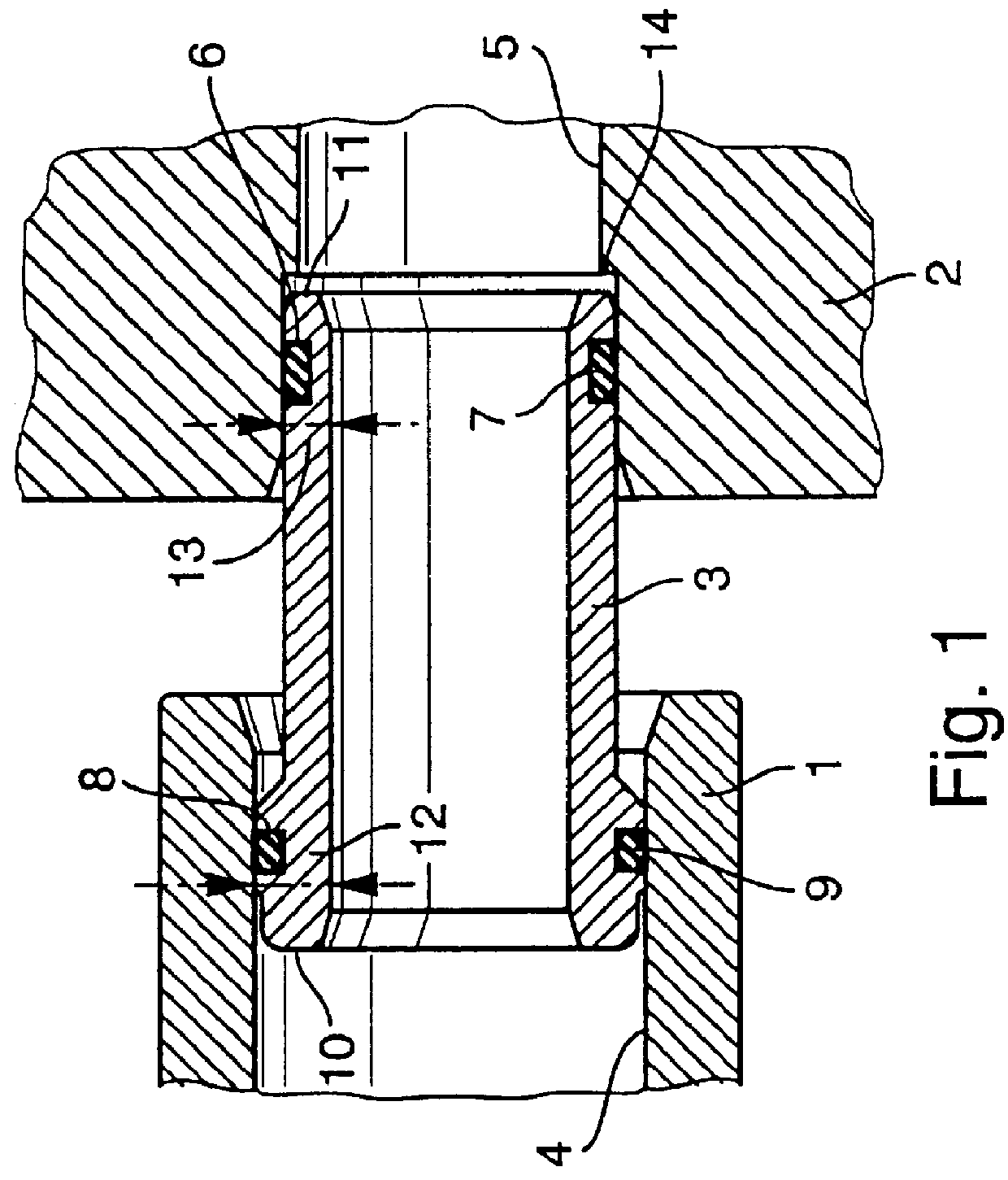
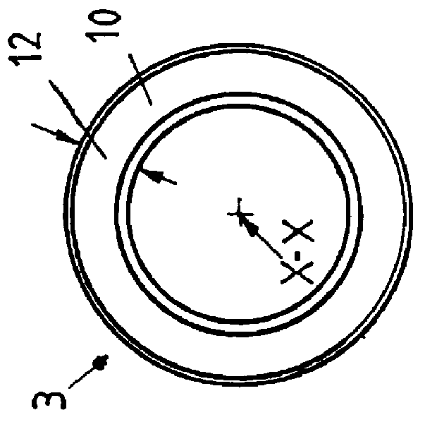
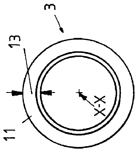
Referring first to FIG. 1, there is shown a structure which can be utilized with advantage in a starting clutch (such as the starting clutch 20 shown in FIGS. 4 and 4a) of a transmission (such as the transmission 99 shown in FIG. 4a). The structure of FIG. 1 compises a first component 1 (e.g., a hollow rotary cylindrical shaft corresponding to the part 98 shown in FIG. 4a), a second component 2 which may but need not be stationary (i.e., which may but need not rotate when the transmission 99 embodying the structure of FIG. 1 or 4a is in use), and an elongated cylindrical tube or conduit 3 between the components 1 and 2 (this conduit can correspond to the part 25 shown in FIGS. 4 and 4a). In the embodiment of FIG. 1, the first component 1 is rotatable about the central longitudinal axis X--X of the conduit 3, and such axis coincides with the axis of the second component 2.

The first component 1 is provided with a socket 4 in the form of the end portion of an axial bore which serves to...


PUM


Abstract

A transmission for use in the power train of a motor vehicle has a rotary first component (such as a shaft), a second component which may but need not be rotatable, a fluid-conveying conduit having a first end portion extending into a first socket provided in the first component and a second end portion extending into a socket of the second component, a split-ring piston packing located in an external groove of the first end portion, and an O-ring received in an external groove of the second end portion. The O-ring prevents the conduit and the second component from rotating relative to each other. A passage which is defined by the two components and the conduit can receive a stream of pressurized hydraulic fluid from a pump by way of pipes wherein the flow of fluid is controlled by several valves including a manually operated slide valve, at least one preferably adjustable pressure regulating valve, at least one preferably adjustable safety valve, and adjuster for the adjustable valve or valves; such adjuster can employ one or more signal-responsive control valves.

Description

The present invention relates to improvements in transmissions which can be employed with advantage in the power trains of motor vehicles to transmit torque from a prime mover (such as an internal combustion engine) to the wheels. More particularly, the invention relates to improvements in transmissions which comprise clutches, actuators, torque sensors, pulleys, belts or chains and / or other parts controlled by systems of pumps, valves and other fluid flow initiating and regulating devices.It is often necessary to convey a fluid (e.g., oil or another hydraulic fluid) between parts which must move with and / or relative to each other, e.g., between a stationary component and a rotary component or between two components which can or must or should rotate at different speeds an / or in different directions. Transmissions wherein a conduit, a pipe, a hose or an analogous fluid conveying component must confine a stream of a fluid to flow between two spaced-apart components which can or shoul...

Claims


Application Information

Patent Timeline
IPC IPC(8): F16D25/00F16D48/00F16D48/06F16D25/12F16L21/02F16L27/12F16L21/04F16H61/66F16H61/02F16H61/662F16H47/00
CPCF16D25/123F16D48/066F16L21/04F16L27/125B60W2710/027F16H61/0206F16H57/0473F16H2061/0046F16H61/662F16D2048/0203F16D2048/0281F16D2500/1026F16D2500/30415F16D2500/30426F16D2500/5104F16D2500/70217F16D2500/70223F16D2500/70294F16D2500/70615F16D2500/70626
Inventor FRIEDMANN, OSWALDWALTER, BERNHARDHOMM, MANFREDREUSCHEL, MICHAEL
Owner SCHAEFFLER TECH AG & CO KG
Why Eureka
Try Eureka