

Resolution enhancing image display apparatus
- Summary
- Abstract
- Description
- Claims
- Application Information
AI Technical Summary
Benefits of technology
Problems solved by technology
Method used
Image

Examples
examples 1 to 6
and Numerical Examples 1 to 5 of the image display apparatus according to the present invention will be described below.
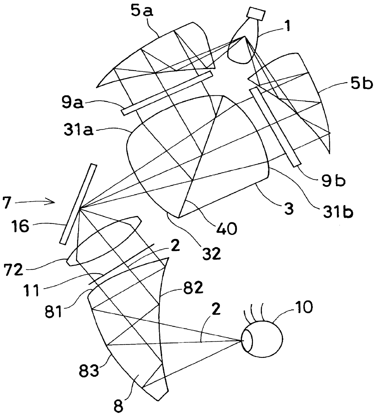
In the following examples and numerical examples, reference numerals denote respective constituent elements as follows. Reference numeral 1 denotes a light source; 2 an optical axis; 3, 3' composite optical systems; 4 an optical coupling / separating element; 5 an illuminating optical system; 6 a viewing optical system; 7 a relay optical system; 8 an ocular optical system; 9 an image display device; 10 an observer's eyeball; 11 an intermediate image of the image display device; 13 a light beam; 15 an exit pupil; 16 a reflecting mirror; 31 a first surface of the composite optical system; 32 a second surface of the composite optical system; 33 a third surface of the composite optical system; 34 a fourth surface of the composite optical system; 40, 40' optical coupling / separating surfaces; 41 an entrance surface of the optical coupling / separating element; 42 an exit sur...
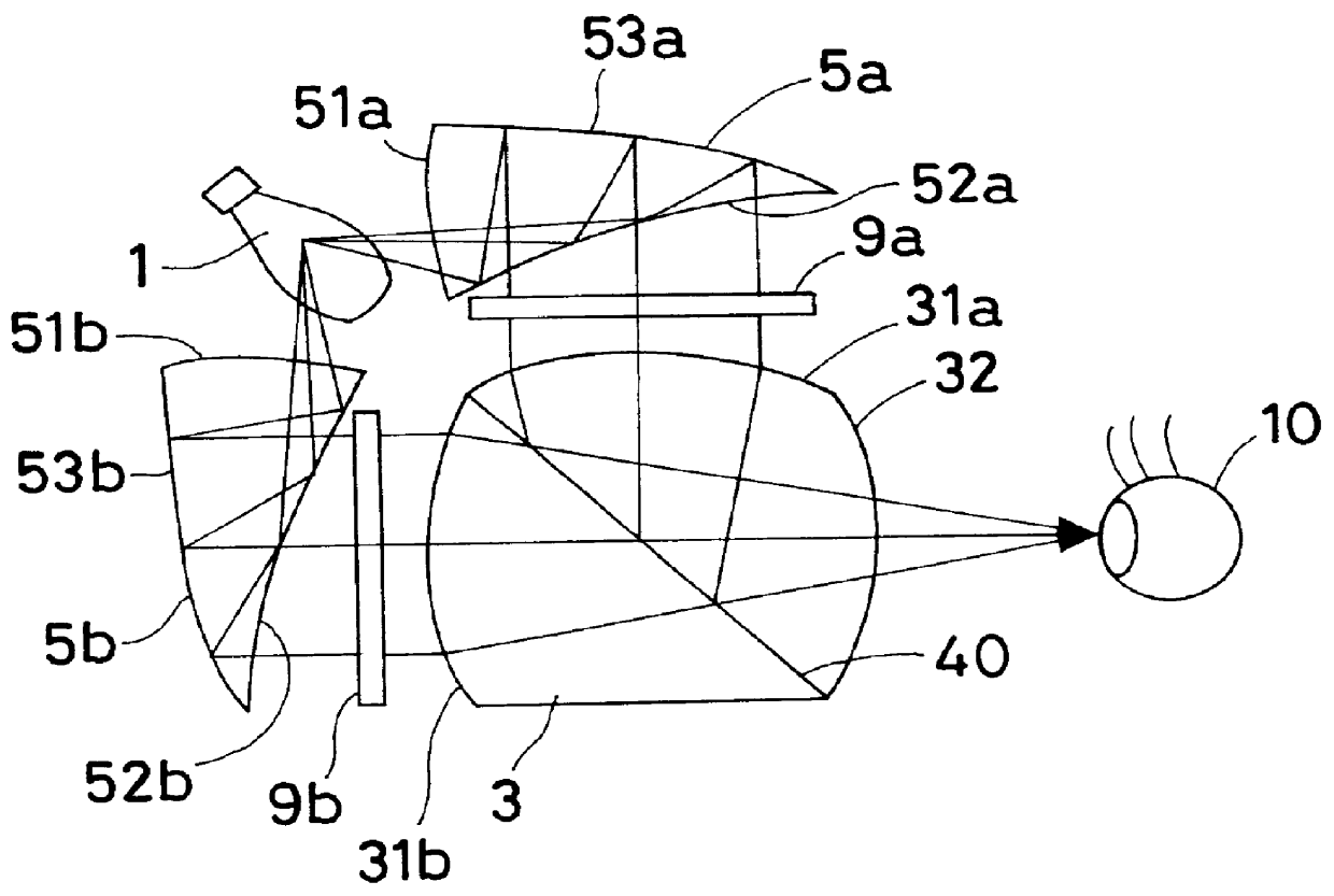
example 1
of the image display apparatus according to the present invention is shown in FIG. 1. In the figure, illuminating optical systems 5a and 5b respectively have first surfaces 51a and 51b through which light emitted from a light source 1 enter the illuminating optical systems 5a and 5b, second surfaces 52a and 52b facing opposite to the first surfaces 51a and 51b and having both reflecting and transmitting actions, and third surfaces 53a and 53b, which are reflecting surfaces. A space formed between the three surfaces 51a, 52a and 53a and a space formed between the three surfaces 51b, 52b and 53b are each filled with an optical plastic material that is a substantially transparent optical medium having a refractive index of approximately 1.5. The illuminating optical systems 5a and 5b illuminate the respective display surfaces of transmissive liquid crystal display devices 9a and 9b as image display devices from the rear.
The transmissive liquid crystal display devices 9a and 9b are twis...
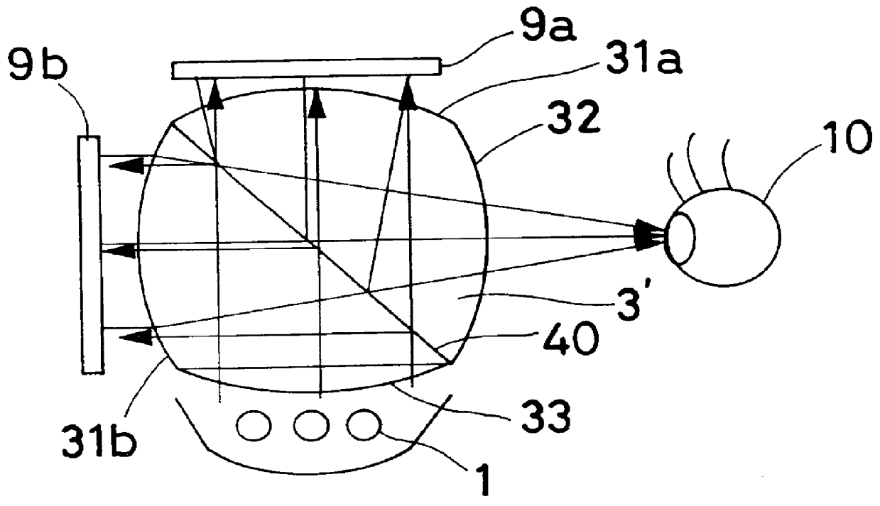
example 2
of the image display apparatus according to the present invention is shown in FIG. 2. Referring to the figure, the image display apparatus has two reflective liquid crystal display devices 9a and 9b and a composite optical system 3' in which a polarizing half-mirror surface 40 as an optical coupling / separating surface is placed in an optical plastic material that is a transparent optical medium having a refractive index of approximately 1.5. The composite optical system 3' has an entrance surface 33 through which light from a light source 1 enters the optical system 3', entrance surfaces 31a and 31b through which image light from the image display devices 9a and 9b enters the optical system 3', and an exit surface 32 on the observer side. All the surfaces 31a, 31b, 32 and 33 have a positive power. The optical system 3' performs the functions of an optical coupling / separating element, an illuminating optical system and a viewing optical system, as has been stated above.
A polarizing h...
PUM
 Abstract
Description
Claims
Application Information