Torsional vibration damper

a torsional vibration and damper technology, applied in the direction of clutches, mechanical devices, couplings, etc., can solve the problems of spring cups and/or springs being destroyed, the angular angle of the cups is apt to change, and the damper or the twin-mass flywheel is interfered with

Inactive Publication Date: 2000-10-17
LUK LAMELLEN & KUPPLUNGSBAU BETEILIGUNGS KG
View PDF7 Cites 53 Cited by
  • Summary
  • Abstract
  • Description
  • Claims
  • Application Information

AI Technical Summary

Benefits of technology

An object of the present invention is to provide spring cups or spring abutments which render it possible to establish satisfactory supports for the end portions of the springs which cooperate therewith and to est

Problems solved by technology

However, when utilized in conjunction with spring-receiving chambers which do not conform to the outer diameters of the springs and/or which are not substantially complete in the circumferential direction, such spring cups are apt to change their angular positi

Method used


Image

  • Torsional vibration damper
  • Torsional vibration damper
  • Torsional vibration damper

Examples


Embodiment Construction

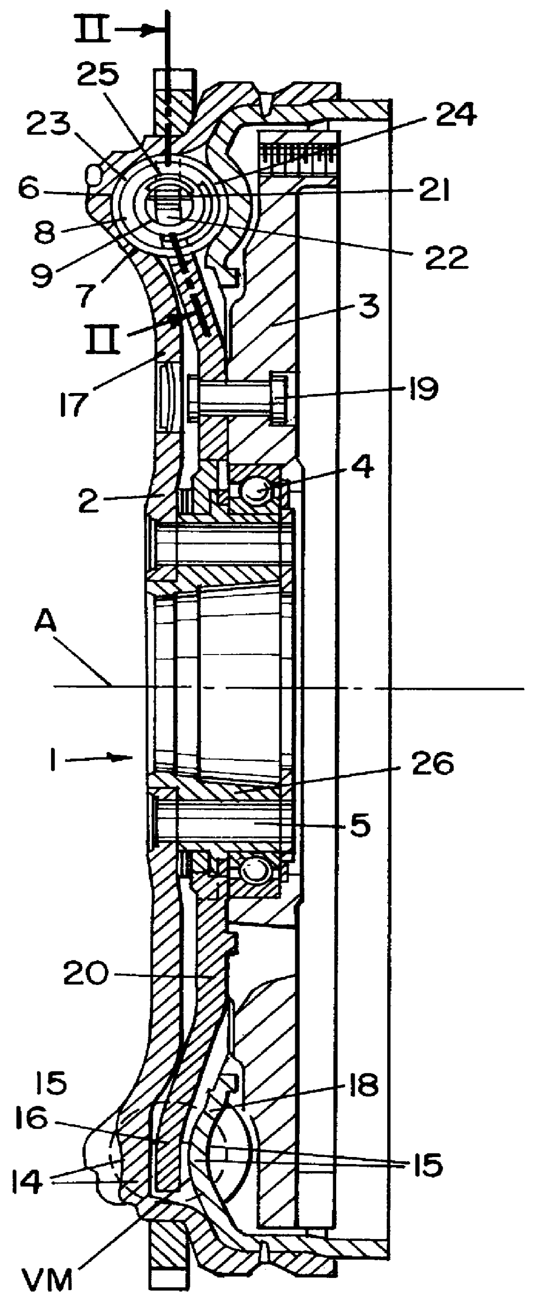
The torsional vibration damping apparatus of FIGS. 1 and 2 comprises a split flywheel 1 which includes a first or primary flywheel mass or structural element 2 adapted to be affixed to a non-illustrated output shaft of a combustion engine, as well as a second or secondary flywheel mass or structural element 3. The second flywheel mass 3 can be connected, with the interposition of a clutch disc, to a friction clutch which can couple the output shaft with or can disengage the output shaft from an input shaft (not shown) of a transmission. The flywheel masses 2 and 3 are mounted for rotation relative to each other about a common axis A on an antifriction ball bearing 4 which, in the embodiment of FIGS. 1 and 2, is disposed radially outwardly of axially parallel bores 5 for the introduction of fastening screws serving to mount the first flywheel mass 2 on the output shaft of a combustion engine.

A damping arrangement 6 which operates between the two flywheel masses 2 and 3 comprises ener...


PUM


Abstract

A composite flywheel has primary and secondary masses rotatable relative to each other against the resistance of a damper having arcuate coil springs and an abutment between neighboring end portions of such springs. The abutment can move in the circumferential direction of the masses and is preferably form-lockingly connected against loss to at least one of the springs. To this end, a portion of the abutment extends into the adjacent convolutions of the at least one spring and is engaged by such convolutions with a force which suffices to prevent unintentional separation of the at least one spring from the abutment in the axial direction of the at least one spring.

Description

The present invention relates to dampers in general, and more particularly to improvements in torsional vibration dampers of the type having at least two structural elements which are rotatable relative to each other about a common axis against the resistance of at least one energy storing device. The structural elements comprise stressing portions which serve to compress the at least one energy storing device when at least one of the structural elements is caused to turn relative to the other structural element or elements. Each energy storing device comprises at least one coil spring, and at least one of the two end portions of the coil spring cooperates with an abutment which is turnable relative to the structural elements and serves as a support for the corresponding end portion of the coil spring.Published German patent application No. 36 10 127 discloses a torsionally elastic vibration damping clutch which constitutes a twin-mass flywheel wherein torsionally elastic or vibrati...

Claims


Application Information

Patent Timeline
IPC IPC(8): F16F15/131F16F15/134
CPCF16F15/1343
Inventor JACKEL, JOHANNBIRK, ALBERT
Owner LUK LAMELLEN & KUPPLUNGSBAU BETEILIGUNGS KG
Why Eureka
Try Eureka