

Undercut-engaging dowel
a technology of undercut and engaging dowels, which is applied in the direction of bolts, dowels, fastening means, etc., can solve the problems of affecting the displacement resistance of undercut-engaging dowels, the resistance of these dowels to displacement under load is very weak, and the cost associated with anchoring of undercut-engaging dowels in bores with preliminary formed undercuts is rather high
- Summary
- Abstract
- Description
- Claims
- Application Information
AI Technical Summary
Benefits of technology
Problems solved by technology
Method used
Image

Examples
Embodiment Construction
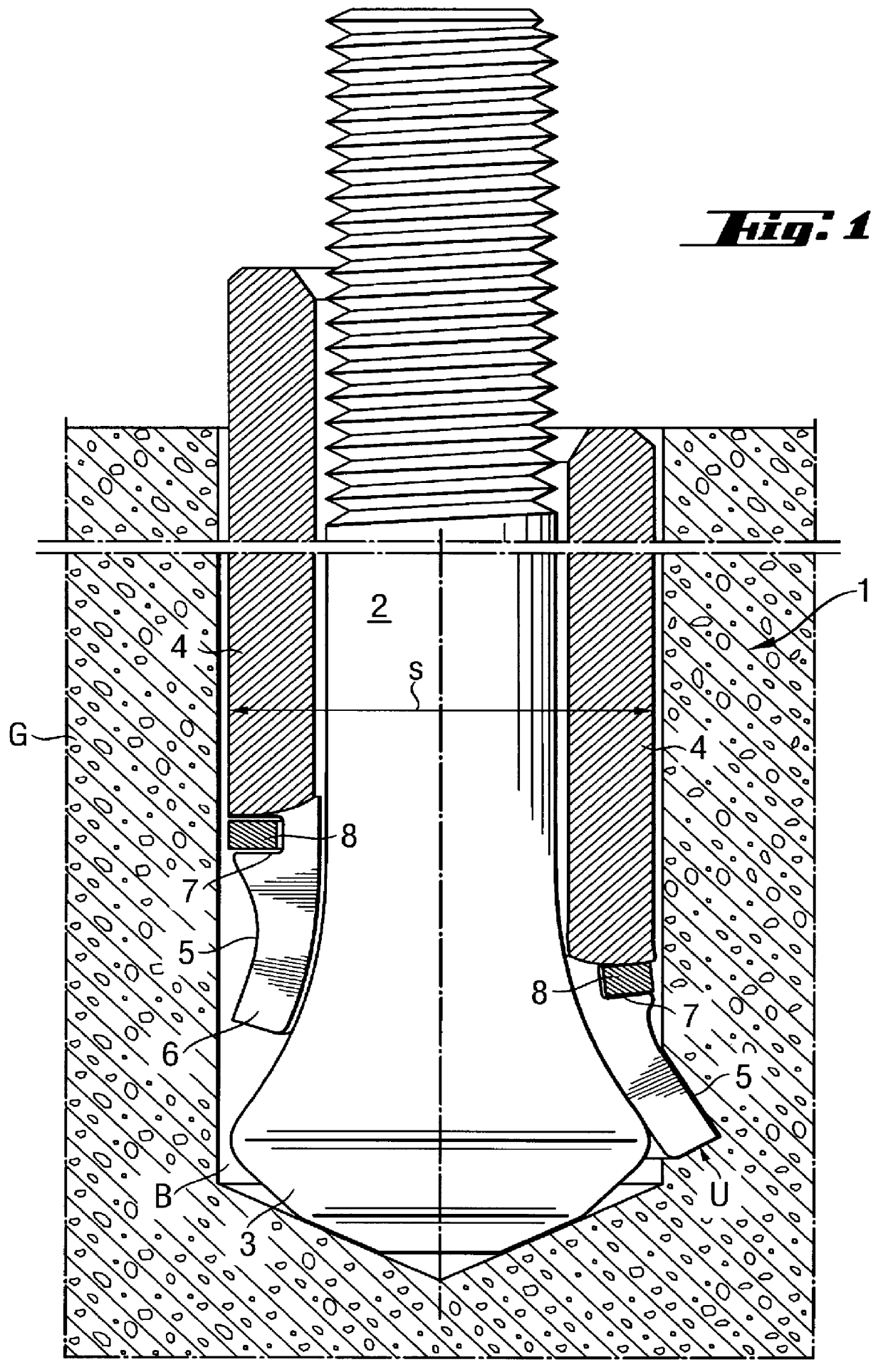
In FIGS. 1 and 4, the left half of a respective drawing shows a dowel according to first and second embodiments, respectively, of the present invention in its initial position. The right half of the respective drawing shows the undercut self-cutting dowel in its anchoring position with its expansion tabs being radially expanded. The dowel, which is shown in FIG. 1, is generally designated with a reference numeral 1. The dowel 1 is anchored in a bore B formed in a structural component G formed, e.g., of concrete. The dowel 1, which is shown in FIG. 1, includes an anchor rod 2 provided at its rear, in the use position, end with load application means 2a, e.g., an outer or inner thread. At its opposite, front end, the anchor rod 2 has a head 3 the outer diameter of which increases toward a free end of the anchor rod 2 conically or trumpet-like. An expansion sleeve 4 is displaceably supported on the anchor rod 2. The expansion sleeve 4 has a central bore through which the anchor rod 2 e...
PUM
 Abstract
Description
Claims
Application Information