Color cathode ray tube having shadow mask with prescribed bridge widths

a color cathode ray tube and shadow mask technology, applied in the direction of cathode ray tubes/electron beam tubes, electric discharge tubes, electrical apparatus, etc., can solve the problems of small landing dislocation, difficult to restrict local doming, and landing dislocation caused by howling, so as to reduce local doming and vibration of shadow masks, and hinder color blurring

Inactive Publication Date: 2000-10-17
KK TOSHIBA
View PDF5 Cites 14 Cited by
  • Summary
  • Abstract
  • Description
  • Claims
  • Application Information

AI Technical Summary

Benefits of technology

The present invention has been made in view of the above problem and its object is to provide a color cathode ray tube capable of reducing local doming and vibration of a shadow mask and hinders color blurring.

Problems solved by technology

However, in a color cathode ray tube of a shadow mask type, only 1 / 3 or less of the entire electron beams emitted from the electron gun reach the phosphor screen, and the other remaining beams collide onto the shadow mask.
Therefore, doming which occurs in the peripheral portion of the mask body is of a low level and causes only a small landing dislocation.
Therefore, it is difficult to restrict local doming which occurs in a relatively short time and to eliminate a landing dislocation, only by means of enlarging the curvature of the shadow mask in its horizontal cross-section.
Therefore, such a landing dislocation caused by howling must be restricted.
However, in the intermediate regions of the mask body as described above, the vibration is large and a landing dislocation has the largest amount.

Method used


Image

  • Color cathode ray tube having shadow mask with prescribed bridge widths
  • Color cathode ray tube having shadow mask with prescribed bridge widths
  • Color cathode ray tube having shadow mask with prescribed bridge widths

Examples


Embodiment Construction

In the following, a color cathode ray tube according to an embodiment of the present invention will be described in details with reference to the accompanying drawings.

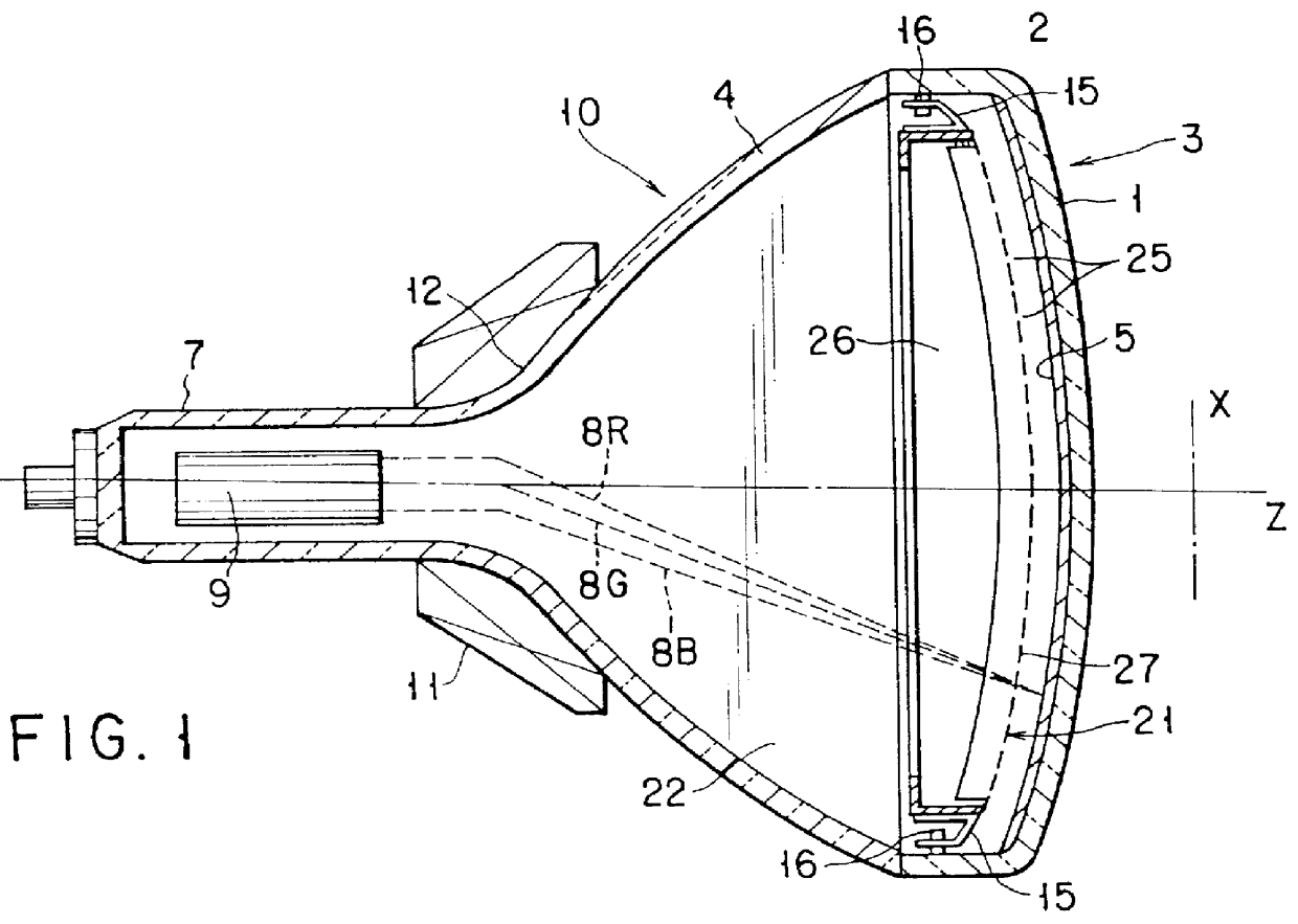
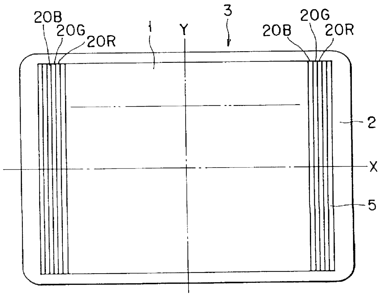
As shown in FIGS. 1 and 2, the color cathode ray tube comprises a vacuum envelope 10 made of glass. The vacuum envelope 10 includes a face panel 3 having a substantially rectangular effective portion 1 and a skirt portion 2 provided on the peripheral portion of the effective portion, a funnel 4 connected with the skirt portion 2, and a cylindrical neck 7 projecting from the funnel 4.

The effective portion 1 has a substantially rectangular shape having a horizontal axis (or long axis) X and a vertical axis (or short axis) perpendicular to each other, extending through a tube axis Z of the cathode ray tube. In addition, the inner surface of the effective portion 1 is formed of a concave curved surface which is not spherical. On the inner surface of the effective portion 1 is formed a phosphor screen 5 which includes thre...


PUM


Abstract

PCT No. PCT/JP97/04687 Sec. 371 Date Aug. 18, 1998 Sec. 102(e) Date Aug. 18, 1998 PCT Filed Dec. 18, 1997 PCT Pub. No. WO98/27573 PCT Pub. Date Jun. 25, 1998A shadow mask opposed to a phosphor screen has a substantially rectangular effective surface (30) where slit-like apertures are formed. The apertures are disposed so as to constitute a plurality of aperture rows which extend in parallel with the short axis of the effective surface and are disposed in the long axis of the effective surface. Each of the aperture rows includes a plurality of aperture, and bridges (38) positioned between any adjacent pair of the apertures. The width B of the bridges in the lengthwise direction of the aperture rows, positioned an intermediate between the short axis of the effective surface and a short side edge thereof is greater than that of the bridges positioned at a peripheral portion of the effective surface.

Description

The present invention relates to a color cathode ray tube and particularly to a color cathode ray tube comprising a shadow mask having a number of apertures.In general, a color cathode ray tube comprises a vacuum envelope having a face panel, a phosphor screen formed on an inner surface of the face panel and including three color phosphor layers capable of radiating in blue, green, and red, a shadow mask opposed to the phosphor screen, and an electron gun provided in a neck of the vacuum envelope. The shadow mask includes a mask body having a number of apertures for passing electron beams, and a mask frame supporting the peripheral edge portion of the mask body. In this color cathode ray tube, three electron beams emitted from the electron gun scan the phosphor screen through the shadow mask, thereby displaying a color image.The shadow mask is provided to select the three electron beams to be respectively landed on predetermined positions on the three color phosphor layers, and this...

Claims


Application Information

Patent Timeline
Patent Type & Authority Patents(United States)
IPC IPC(8): H01J29/07
CPCH01J29/07H01J29/076H01J2229/0788H01J2229/075H01J2229/0744
Inventor MURAI, TAKASHISAOTOME, ICHIROTANI, MUNECHIKA
Owner KK TOSHIBA
Why Eureka
Try Eureka