Aircraft wing leading edge high lift device with suction

a technology of high lift and aircraft wings, applied in the direction of mechanical equipment, airflow influencers, transportation and packaging, etc., can solve the problems of reducing the growth rate of the boundary layer, reducing the drag of the aircraft, and reducing the drag

a technology of high lift and aircraft wings, applied in the direction of mechanical equipment, airflow influencers, transportation and packaging, etc., can solve the problems of reducing the growth rate of the boundary layer, reducing the drag of the aircraft, and reducing the drag

US6135395AInactive Publication Date: 2000-10-24AIRBUS OPERATIONS LTD

Image

  • Aircraft wing leading edge high lift device with suction
  • Aircraft wing leading edge high lift device with suction
  • Aircraft wing leading edge high lift device with suction

Examples


Embodiment Construction

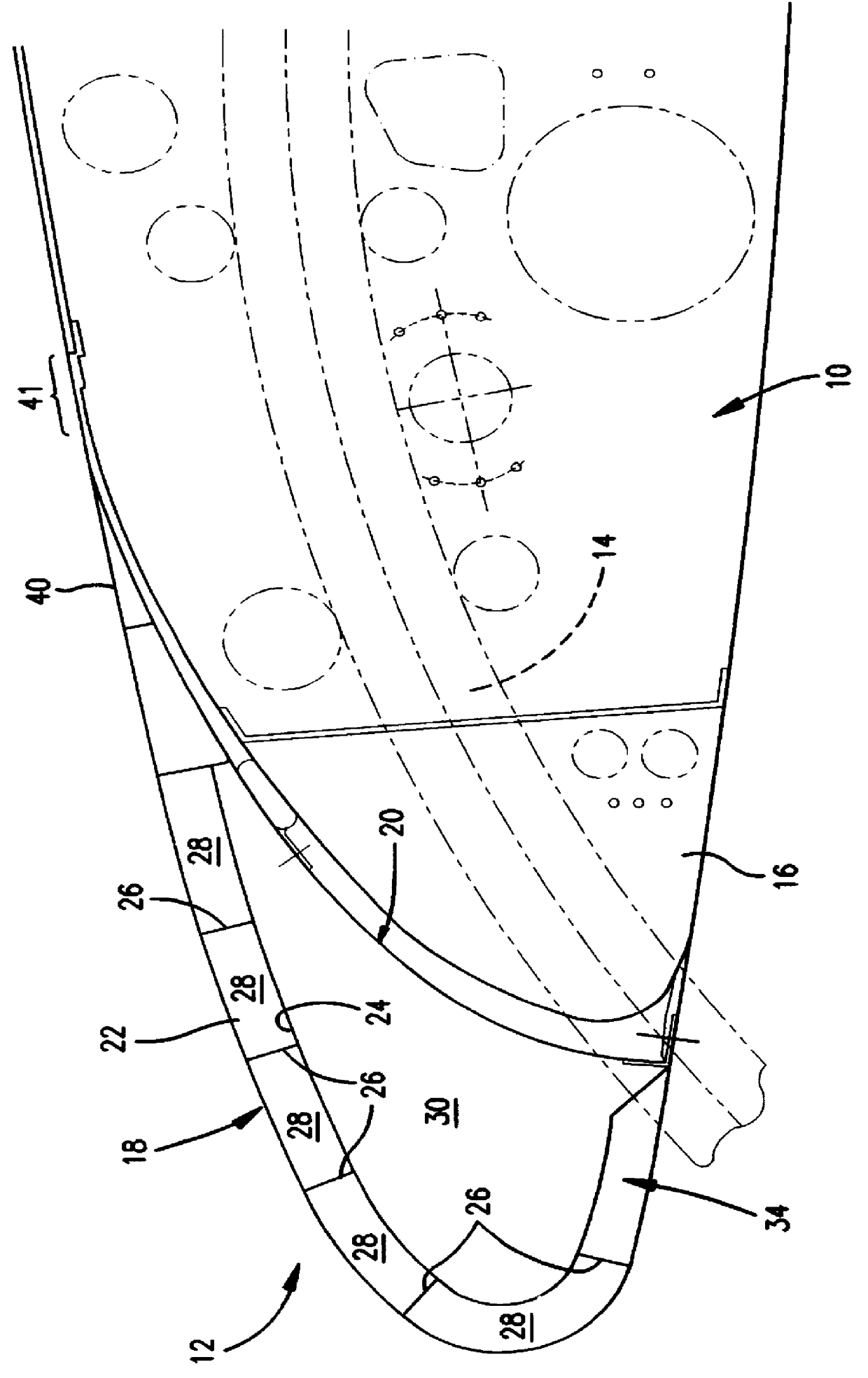
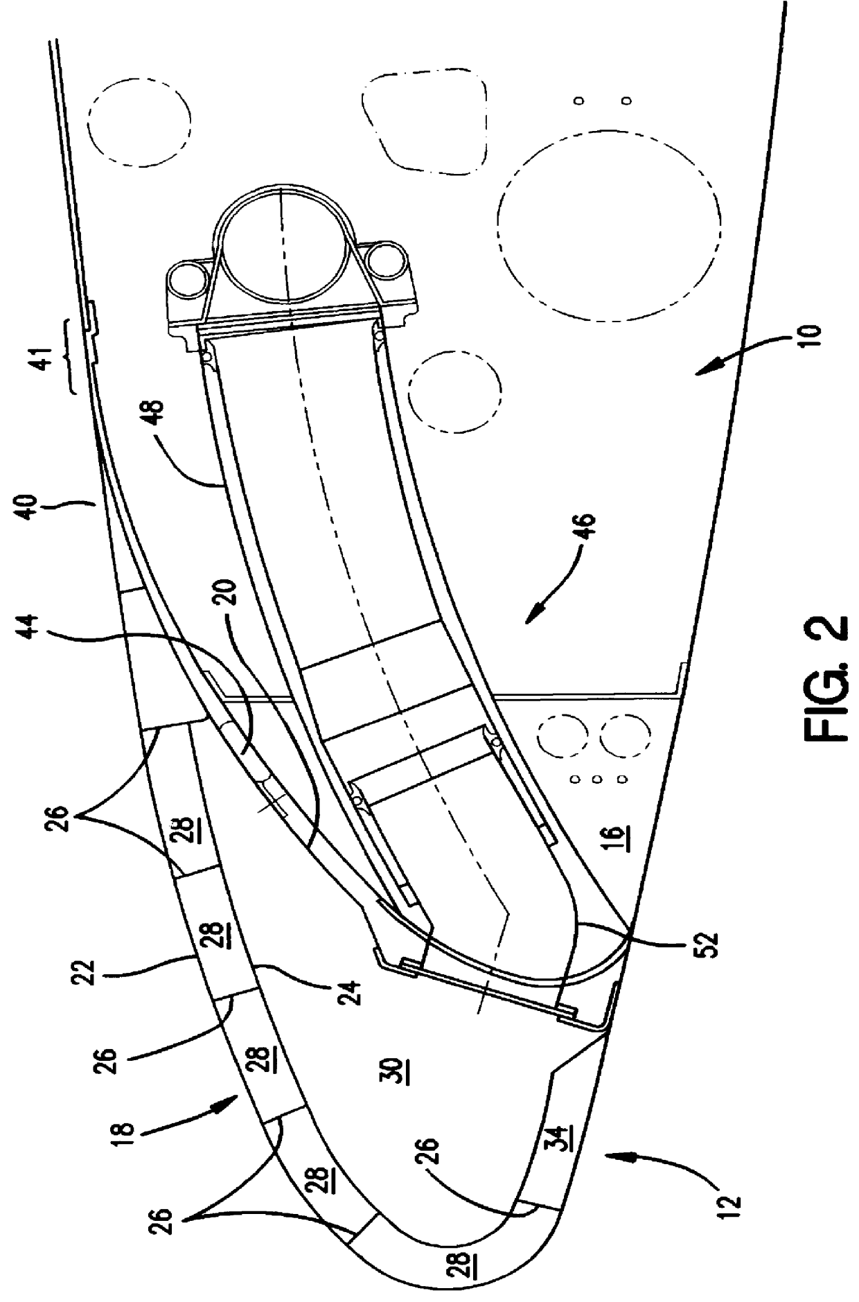
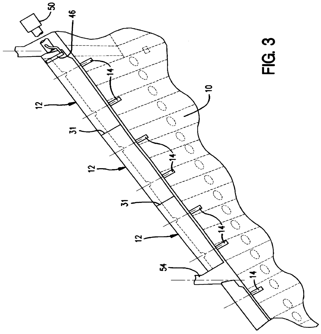
Referring to the Figures, the wing assembly comprises a relatively fixed main wing portion 10 and a relatively moveable leading edge slat 12 mounted on the main wing portion 10 by means of curved track extension / retraction mechanisms shown generally at 14, for movement between the position shown in FIG. 1 in which the leading edge slat 12 merges generally smoothly with the main wing portion 10 and a high lift, deployed, configuration in which it is extended forwardly and downwardly to increase the camber and effective surface area of the wing and thus the lift produced. It will be seen from FIG. 1 that the D nose portion 16 of the main wing is of relatively small transverse section and that some of this area is occupied by the extension / retraction mechanism.

In this arrangement, boundary layer control is effected by applying suction through the leading edge slat 12 rather than to the main wing portion 10. Thus the ducting and services required for the boundary layer control (with the...


PUM


Abstract

An aircraft wing, wing assembly and method of reducing drag are provided. The wing asembly includes a main wing portion (10) and a leading edge high lift portion (12). The high lift portion is movable between a retracted position in which it generally merges with the main wing portion and a deployed position forwardly thereof. At least a substantial part of an upper surface (22) of the high lift portion is air permeable or perforated and in flow communication with a suction passage (30) in it. In flight, suction may be applied to the suction passage to reduce the chordwise extent of the turbulent boundary layer over the upper or lower wing surface.

Description

1. Field of the InventionThis invention relates to an aircraft wing assembly including a leading edge high lift device and in particular to such assemblies incorporating means for reducing the chordwise extent of the turbulent boundary layer over at least one of the upper and lower wing surfaces. The invention also extends to aircraft including such wing assemblies, to high lift devices for use in such assemblies, and to methods of reducing the drag associated with a wing having a leading edge high lift device.In this Specification, the terms forward, rearward, upper, lower, chordwise, spanwise, etc., refer to the orientation of an aircraft when in straight and level flight.2. Discussion of the Prior ArtGreat effort and expense has been expended by aircraft designers and aerodynamicists to reduce as much as possible the drag of the aircraft and particularly the drag experienced by the flow of air over the surface or skin of the aircraft. Typical measures have included making the sur...

Claims


Application Information

Patent Timeline
24 Oct 2000
Publication
US6135395A
IPC
B64C21/00; B64C21/06; B64C9/22; B64C9/00; F15D1/12
CPC
B64C9/22; B64C21/06; B64C2230/22; Y02T50/32; B64C2230/04; Y02T50/166; Y02T50/30; Y02T50/10
Inventors
COLLETT, EDWARD