Method of producing optical disc of bonded type

a technology of optical discs and bonded layers, which is applied in the field of producing optical discs of bonded types, can solve the problems of difficult to uniformly measure the thickness of intermediate layers, difficult to process sheets in line with the size of inner and outer diameters of discs, and high cos

Inactive Publication Date: 2000-10-24
PIONEER CORP +1
View PDF8 Cites 57 Cited by
  • Summary
  • Abstract
  • Description
  • Claims
  • Application Information

AI Technical Summary

Problems solved by technology

However, in case of the former method, there is a problem that air bubbles are easily entrapped in the intermediate layer and it is difficult to uniform the thickness of the intermediate layer.
In case of the latter method, although

Method used


Image

  • Method of producing optical disc of bonded type
  • Method of producing optical disc of bonded type
  • Method of producing optical disc of bonded type

Examples


first embodiment

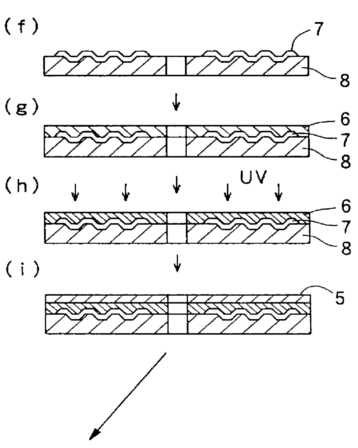
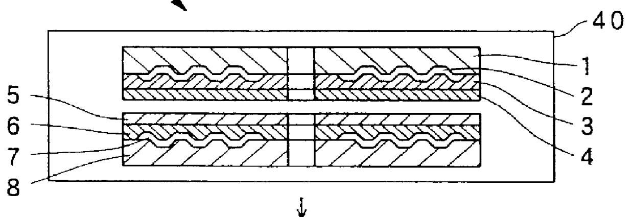
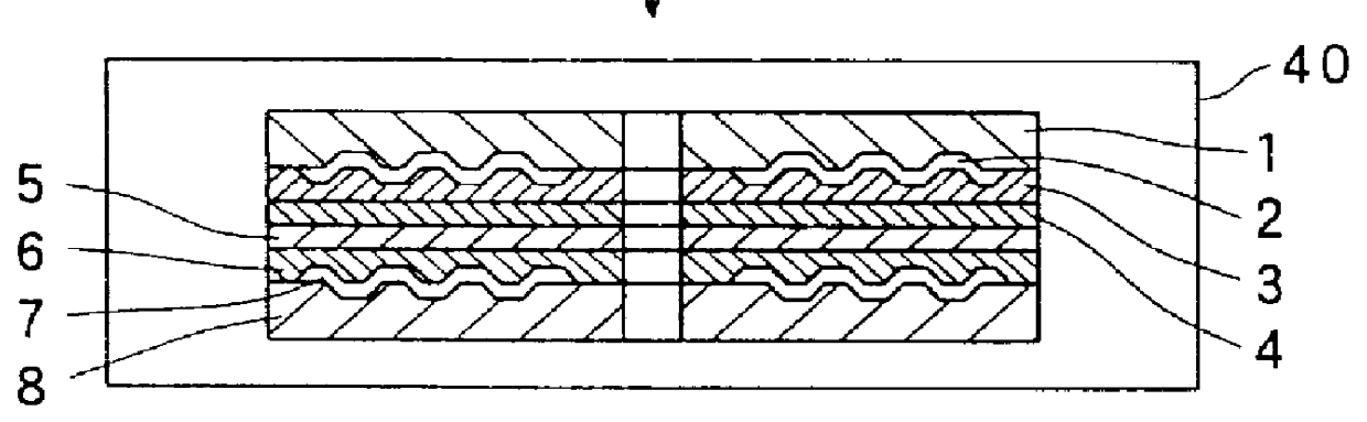
FIG. 1 is a process diagram showing a producing method of the present invention.

In this producing method, at first, a first transparent substrate 1, on one surface of which a pit 9 for carrying a first information signal is formed, and a second transparent substrate 8, on one surface of which the pit 9 for carrying a second information signal is formed, are prepared by injection-molding a transparent resin such as polycarbonate (PC) by use of a metal mold in a cavity of which a stamper is disposed.

The material of the first and second transparent substrates 1 and 8 may be a material having a light transmissivity e.g., a transparent resin such as polycarbonate, polymethyl-methacrylate (PMMA) or the like, or a transparent material such as an optical glass. Among those transparent material, the polycarbonate is excellent in the environment-proof property and in the size stability, and is preferably used.

In case that the first and second transparent substrates 1 and 8 are made of the res...

second embodiment

FIG. 2 is a process diagram showing a producing method of the present invention.

According to the second embodiment, the number of the steps required in the producing method can be reduced as compared with the above described first embodiment, while obtaining the advantageous effect of the present invention.

In the second embodiment, the preparation of the first and second transparent substrates 1 and 8 are the same as the first embodiment.

Next, as shown in a step (a') of FIG. 2, a half-transparent (half-reflective) first reflection film 2 for partially reflecting an incident light and partially transmitting the incident light is formed on the first information record surface of the first transparent substrate 1 where the pit 9 is formed. Here, the first reflection film 2 is formed by a spattering method or the like except for the inner and outer circumferential non-recordable portions, in the same manner as the first embodiment.

The first reflection film 2 having the half transparent ...


PUM

PropertyMeasurementUnit
Temperatureaaaaaaaaaa
Pressureaaaaaaaaaa
Viscosityaaaaaaaaaa

Abstract

A method of producing an optical disc of bonded type includes the processes of: (A) forming a first reflection film, which is half transparent for partially reflecting and partially transmitting an incident light, on a first information record surface of a first transparent substrate; (B) forming a second reflection film, which has a reflective index higher than that of the first reflection film, on a second information record surface of a second transparent substrate; (C) dripping a liquid resin of ultraviolet hardening type onto one of the first and second reflection films by a spin coating method to form a first resin layer in a non-hardened condition; (D) dripping a liquid resin of ultraviolet hardening type onto the other of the first and second reflection films by a spin coating method; (E) emitting ultraviolet onto the liquid resin dripped by the process (D) to form a second resin layer of ultraviolet hardening type in a hardened condition; (F) provisionally bonding the first and second transparent substrates together in a pressure reduced environment; and (G) hardening the first resin layer by emitting ultraviolet from a side of the first transparent substrate.

Description

1. Field of the InventionThe present invention relates to a method of producing an optical disc of bonded type.2. Description of the Related ArtAn optical disc of bonded type such as a conventional optical video disc is produced by bonding a first substrate having a first information record surface and a second substrate having a second information record surface together by an adhesive or bonding agent, from which an information signal on the first information record surface is read by emitting a laser beam thereto through the first substrate and an information signal on the second information record surface is read by emitting a laser beam thereto through the second substrate. In case of, after reading one of the information record surfaces, reading the other of the information record surfaces, the optical disc is inverted or the optical head is moved to a side of the optical disc facing the other of the information record surfaces.Therefore, there is an optical disc of bonded typ...

Claims


Application Information

Patent Timeline
IPC IPC(8): B29C65/00B29C65/48B29D17/00G11B7/257G11B7/26G11B7/24B32B37/12
CPCB29C65/521B29C65/1406B29C66/452B29D17/005B32B37/0007G11B7/256G11B7/26B29C66/342B29C65/4845B29C65/1435B29C65/1483B29C65/00B29L2017/005B32B37/12B32B2309/68B32B2310/0831B32B2429/02G11B7/24G11B7/2531G11B7/2533G11B7/2534G11B7/2585G11B2007/2571G11B2007/25711G11B2007/25713B29C65/1432B29C66/71B29C66/72321B29C66/1122B29K2069/00B29K2033/12
Inventor MARUYAMA, HARUHISAFUJIMORI, JIROMOTOKAWA, MASAAKI
Owner PIONEER CORP
Why Eureka
Try Eureka