Electric motor and electric power steering apparatus employing the electric motor

a technology of electric motors and steering apparatuses, applied in the direction of magnetic circuit rotating parts, magnetic circuit shape/form/construction, transportation and packaging, etc., can solve the problems of hysteresis loss, great magnetic loss, and motor efficiency deterioration, and the output torque decreases

Inactive Publication Date: 2000-10-31
TOYOTA JIDOSHA KK
View PDF10 Cites 45 Cited by
  • Summary
  • Abstract
  • Description
  • Claims
  • Application Information

AI Technical Summary

Benefits of technology

In the electric motor of the invention, the radially inner side surface of each of the permanent magnets arranged on the outer peripheral surface of the rotor is generally convexed radially inwards in its sectional shape taken on a plane of rotation. The outer peripheral surface of the rotor is provided with the curved recess surfaces for contact with the radially inner side curved surfaces of the permanent magnets. Therefore, the area of contact between each permanent magnet and the rotor can be increased so that the magnetic flux between adjacent permanent magnets is prevented from locally concentrating in the rotor.
Consequently, the magnetic loss in the rotor can be reduced so that the motor efficiency can be improved and the output torque can be increased. Furthermore, the occurrence of a minor loop of magnetic flux of a permanent magnet can also be restrained so that the motor efficiency can be improved and the output torque can be increased. Further, the occurrence of torque ripple and cogging can be substantially limited. Further, since the permanent magnets are partially embedded in the rotor, the air gap formed between the rotor and the stator can be reduced so that the output torque can be increased.
The invention can be realized by changing the shape of the permanent magnets and the shape of the rotor. Therefore, in comparison with an electric motor wherein permanent magnets are enlarged in size to increase the output torque, the electric motor of the invention requires fewer permanent magnets, which are normally expensive, and allows an economical and compact design of the electric motor. Thus, the invention provides a small-size and high-torque output electric motor at a low cost. Furthermore, the invention allows an increase in the area of contact between each permanent magnet and the rotor, so that if each permanent magnet is fixed to the rotor by an adhesive, for example, the adhesion strength can be increased.
If the radially outer side surface of each permanent magnet is shaped similar to a circumferentially divided segment of the peripheral surface of an imaginary cylinder whose center axis coincides with the axis of the rotor, each permanent magnet can be adhered and fixed to the outer peripheral surface of the rotor with high precision by using the radially outer side surface of each permanent magnet as a reference surface. Thus, the electric motor according to the invention is assembled more efficiently.

Problems solved by technology

If magnetic flux locally concentrates in the rotor, a great magnetic loss, otherwise known as hysteresis loss, occurs.
The resulting magnetic loss in the rotor increases the magnetic resistance in the rotor so that the motor efficiency deteriorates and the output torque decreases.
The minor loop of the magnetic flux of the permanent magnets does not contribute to the motor output and, moreover, deteriorates the motor efficiency, thereby reducing the output torque.
If a minor loop protrudes into an air gap portion between the rotor and the stator, the minor loop affects the distribution of other magnetic fluxes, resulting in the promotion of the occurrence of torque ripple and cogging.
However, since this requires a large quantity of expensive permanent magnets, the production cost considerably increases as does the size of the electric motor.
Further, the occurrence of torque ripple and cogging can be substantially limited.

Method used


Image

  • Electric motor and electric power steering apparatus employing the electric motor
  • Electric motor and electric power steering apparatus employing the electric motor
  • Electric motor and electric power steering apparatus employing the electric motor

Examples


Embodiment Construction

A preferred embodiment of the invention will be described in detail hereinafter with reference to the accompanying drawings.

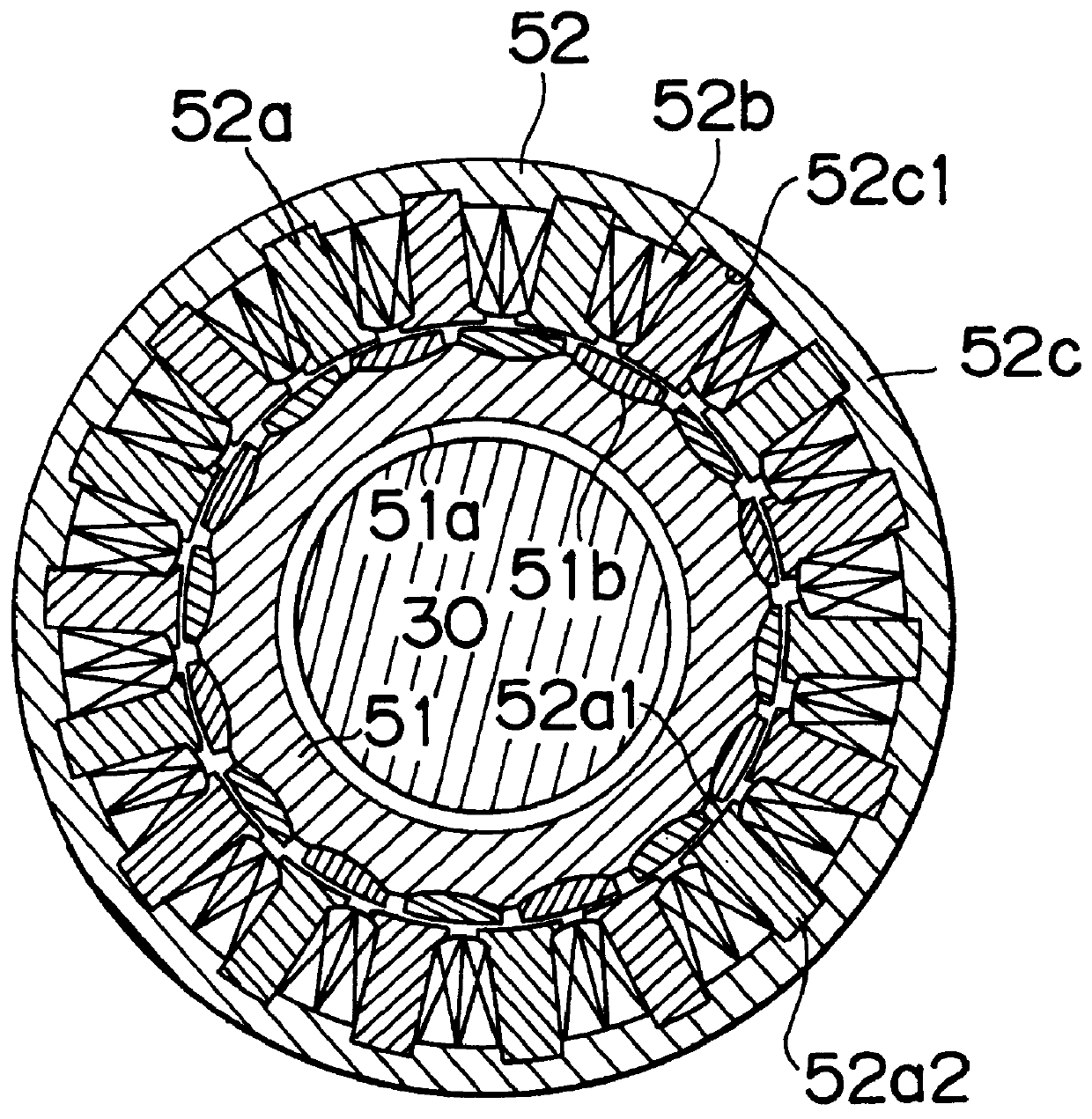
FIG. 1 shows a rack-pinion type steering apparatus having an electric motor 50. The steering apparatus has an input shaft 20, a steering shaft 30, a ball screw mechanism 40, the electric motor 50, and the like mounted to a housing 10 of a vehicle body (not shown). The housing 10 extends in right and left direction relative to the longitudinal, or front to back, direction of the vehicle body.

The input shaft 20 is mounted to the housing 10 to be rotatable, but is prevented from moving in an axial direction of the input shaft 20. At an outer end portion protruding from the housing 10, the input shaft 20 is connected to a steering wheel via a universal joint, an intermediate shaft, a universal joint, a steering main shaft, and the like (none of which are shown) in such a manner that torque can be transmitted therebetween. The input shaft 20 is engaged, at a pinion ...


PUM


Abstract

An electric motor has a rotor for rotation in a stator and a plurality of permanent magnets arranged on an outer peripheral surface of the rotor. A radially inner side surface of each permanent magnet is a curved to generally be convex in a radially inward direction. The outer peripheral surface of the rotor has curved recess surfaces, each of which contacts the radially inner side curved surface of a corresponding permanent magnet so that magnetic flux between adjacent permanent magnets is considerably prevented from locally concentrating within the rotor.

Description

INCORPORATION BY REFERENCEThe disclosure of Japanese Patent Application Nos. HEI 10-235942 filed on Aug. 21, 1998; HEI 10-239224 filed on Aug. 25, 1998; HEI 10-245703 filed on Aug. 31 and HEI 10-247422 filed on Sep. 1, 1998 including the specification, drawings and abstract of each are incorporated herein by reference in their entirety.1. Field of the InventionThe invention relates to an electric motor and an electric power steering apparatus employing the electric motor and, more particularly, to the structure of a stator of the electric motor.2. Description of the Related ArtElectric motors in which a plurality of permanent magnets are arranged on an outer peripheral surface of a rotor provided for rotation in a stator are described in, for example, Japanese Patent Application Laid-Open Nos. HEI 2-111238 and HEI 4-69040. An electric motor as described in these laid-open patent applications is designed to reduce cogging. Cogging is known as the nonuniform variations in torque that ...

Claims


Application Information

Patent Timeline
Patent Type & Authority Patents(United States)
IPC IPC(8): B62D5/04H02K3/52H02K7/06H02K3/46H02K3/32H02K15/095H02K15/12H02K15/08H02K1/27H02K5/14H02K15/00
CPCB62D5/0403H02K1/278H02K3/325H02K3/522H02K7/06H02K15/095H02K15/12H02K2203/12H02K15/0025H02K5/148
Inventor TOMITA, MASAAKIMIZUTANI, RYOJI
Owner TOYOTA JIDOSHA KK
Why Eureka
Try Eureka