Air-cooled condenser

a condenser and air technology, applied in steam/vapor condensers, heat exchange apparatus, tubular elements, etc., can solve the problems of deteriorating the thermal efficiency of the system, requiring degassing, and difficult to correct the arrangement and dimension of the after-cooler 15 and other problems, to achieve the effect of strong cooling

a condenser and air technology, applied in steam/vapor condensers, heat exchange apparatus, tubular elements, etc., can solve the problems of deteriorating the thermal efficiency of the system, requiring degassing, and difficult to correct the arrangement and dimension of the after-cooler 15 and other problems, to achieve the effect of strong cooling

US6142223AInactive Publication Date: 2000-11-07ENERGIAGAZDALKODASI RESZVENYTARSASAG

Image

  • Air-cooled condenser
  • Air-cooled condenser
  • Air-cooled condenser

Examples


Embodiment Construction

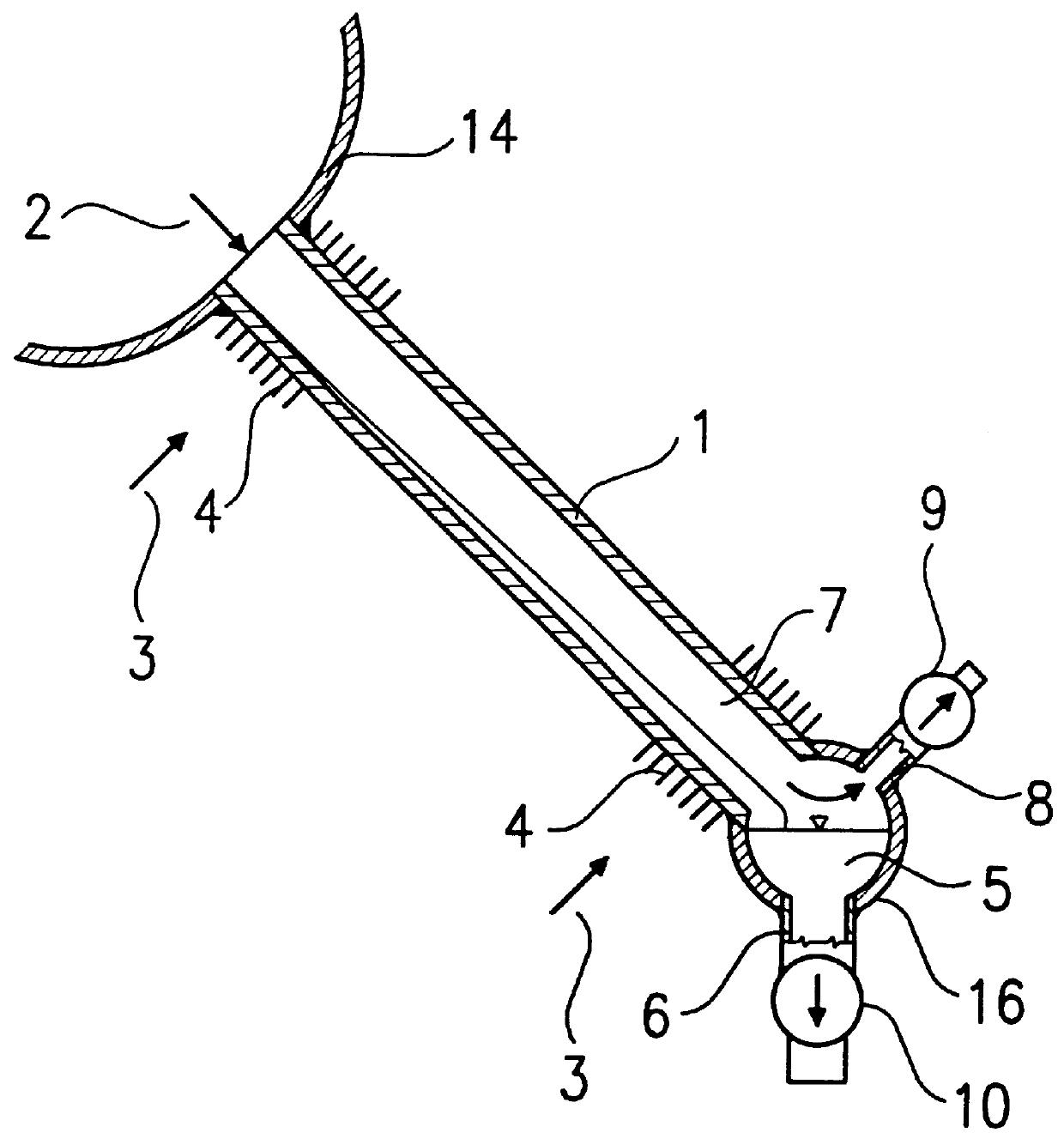
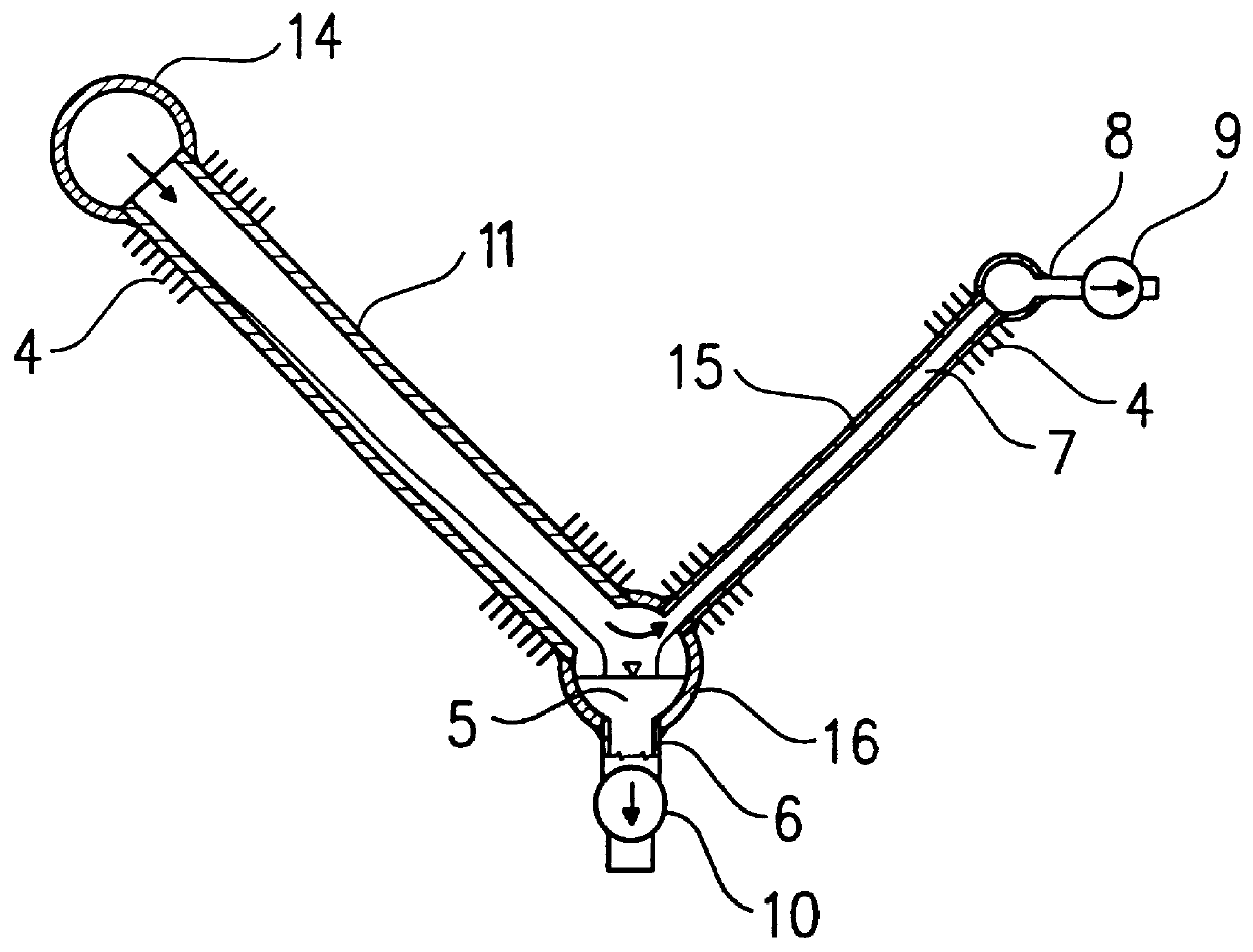
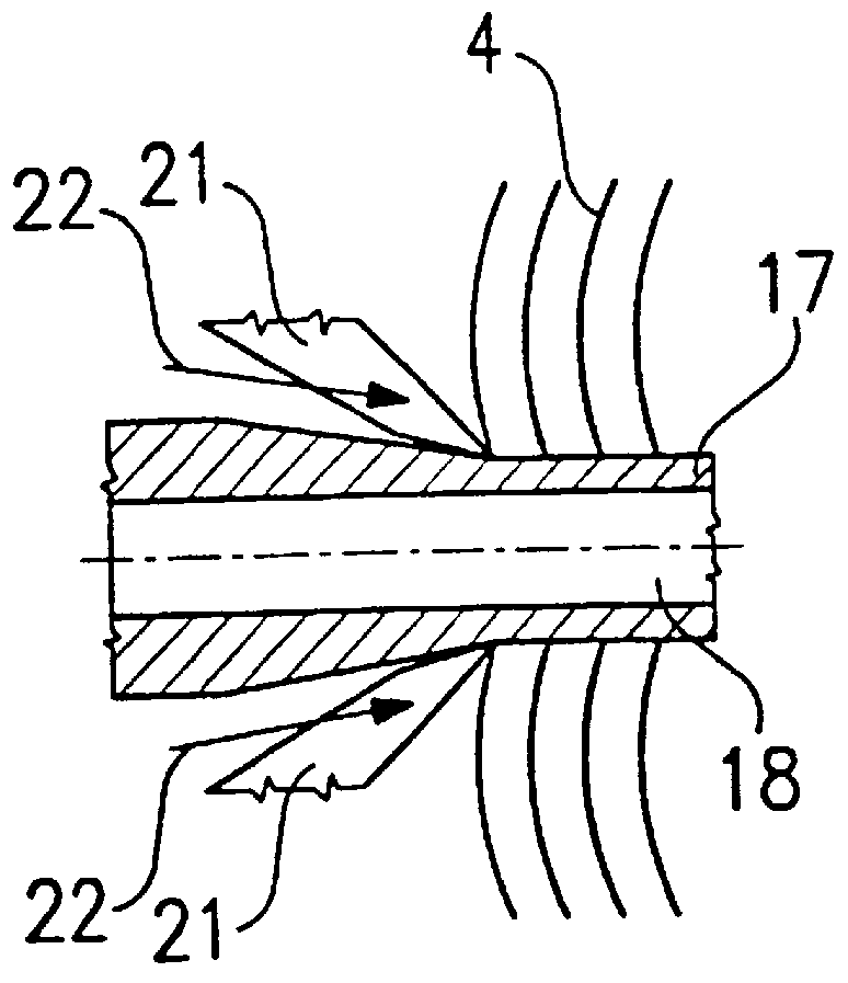
FIGS. 3 and 4 are lateral and longitudinal cross-sectional views, respectively, of a finned tube 17 according to the invention having a flat design with a pair of essentially flat side walls and arched exterior closings, i.e. it has a horse-race track shape. In the interior of the finned tube 17 there are separation walls 18 arranged, which separate internal longitudinal channels 19. Air-side fins 4 are located on the external flat sides of the finned tube 17. The fins 4 are fitted with slots perpendicular to the flow direction, so that a thick boundary layer detrimental to heat transfer may not develop around the finned tube 17.

In FIGS. 5-7 some embodiments of the tube part of the finned tubes 17 are shown. In the embodiment according to FIG. 5, the tube part consists of two halves, and the separation walls 18 are also separate pieces. The separate pieces may be welded, soldered, attached with an adhesive or connected together via mechanical load transmitting fastening.

In the embod...


PUM


Abstract

PCT No. PCT / HU98 / 00008 Sec. 371 Date Sep. 25, 1998 Sec. 102(e) Date Sep. 25, 1998 PCT Filed Jan. 26, 1998 PCT Pub. No. WO98 / 33028 PCT Pub. Date Jul. 30, 1998An air-cooled condenser comprising a distributing chamber for distributing a vaporous medium to be condensed, a condensate collecting chamber and finned tubes with fins on air side, said finned tubes being connected in parallel between the distributing chamber and the condensate collecting chamber, where each of the finned tubes comprises two parallel essentially flat side walls and exterior closings connecting the side walls, in the finned tubes there are longitudinal separation walls connected to the side walls and dividing the inner space of the finned tubes into longitudinal parallel channels, and in the separation walls there are breakthroughs and closure elements for allowing the flow of the medium between neighboring channels.

Description

The invention relates to an air-cooled condenser for condensing a vaporous medium, preferably steam.Condensers are widely used in the manufacturing, chemical and energy industry. The air-cooled condenser is a special type of condenser, which generally operates under a vacuum. First of all we shall describe the physical processes that take place in air-cooled condensers, to make sure that the operation of the air-cooled condenser according to the invention is understood.The description of physical processes and of the prior art apply to power plant steam condensers and to condensing steam, but of course the invention is not restricted to this type of condenser: they can also be used as applicable in other places and for other vaporous mediums where air-cooled condensers are required.Air-cooled steam condensers generally consist of a large number of tubes connected in parallel which are densely finned on the air side. The processes taking place in the parallel tubes are principally id...

Claims


Application Information

Patent Timeline
07 Nov 2000
Publication
US6142223A
IPC
F28F3/00; F28F3/04; F28F1/02; F28F1/24; F28B9/00; F28B1/06; F28B9/10; F28B1/00
CPC
F28B1/06; F28B9/10; F28F3/04; F28F1/022; F28F1/24; F28B2001/065
Inventors
BODAS, JANOS; CSABA, GABOR