Optical sheet lamination

a technology of optical sheets and lamination, applied in the direction of optical light guides, prisms, instruments, etc., can solve the problems of a particular surface light source, the primary function of a prism sheet for improving brightness, and the disassembly of pixels in the image composed of pixels

Inactive Publication Date: 2000-11-14
DAI NIPPON PRINTING CO LTD
View PDF14 Cites 42 Cited by
  • Summary
  • Abstract
  • Description
  • Claims
  • Application Information

AI Technical Summary

Problems solved by technology

In an optical sheet as described above, a pattern where bright and dark parts are alternately repeated by light from a surface light source is observed in case of combination of a light guide means, a diffusing sheet, another optical sheet and the like, and a problem that an image composed of pixels is disarranged has been caused by this in case that such an optical sheet is used in a liquid crystal display apparatus, for example.
On the other hand, a method of forming minute rugged parts satisfying a particular condition on the flat and smooth surface of a prism sheet is also conceivable as disclosed in said Tokkaihei No. 7-151909, but in this case, there is a problem that the primary function of a prism sheet for improving the brightness by collecting light from a surface light source in a particular direction, for example, in the normal direction to the light outputting surface is deteriorated.
Such a prism sheet having a light diffusing sheet laminated on it has a problem that a prism (or lens) part touching the light diffusing sheet is damaged by a rugged part on the surface of the light diffusing sheet and this flaw deteriorates a uniform and flat light-emitting state as a whole.
On the other hand, although a method of forming the prism sheet side of a light diffusing sheet into a flat and smooth surface in the same way as the light inputting surface of said prism sheet is also conceivable, such a method as this has not come to be in practical use since there is a problem that interference fringes or moire patterns are generated between the flat and smooth surface of said light diffusing sheet and the flat and smooth surface of a light guide plate or the flat and smooth surface of a prism sheet.
Hereupon, the reason why the projections of said spherical beads 20 are made 1 .mu.m or more in height from the surface of the coating layer 18 is that a height of less than 1 .mu.m causes a problem that said gap 24 being close to the wavelength of a surface light-source light (visible light) makes color appear, a problem that it becomes difficult to mass-produce light-transmissive beads (acryl beads for example) as a material for the spherical beads 20, and a problem that such fine beads are difficult to be dispersed in a binder (described later) forming the coating layer 18.

Method used


Image

  • Optical sheet lamination
  • Optical sheet lamination
  • Optical sheet lamination

Examples


Embodiment Construction

Next, an embodiment of the present invention is described.

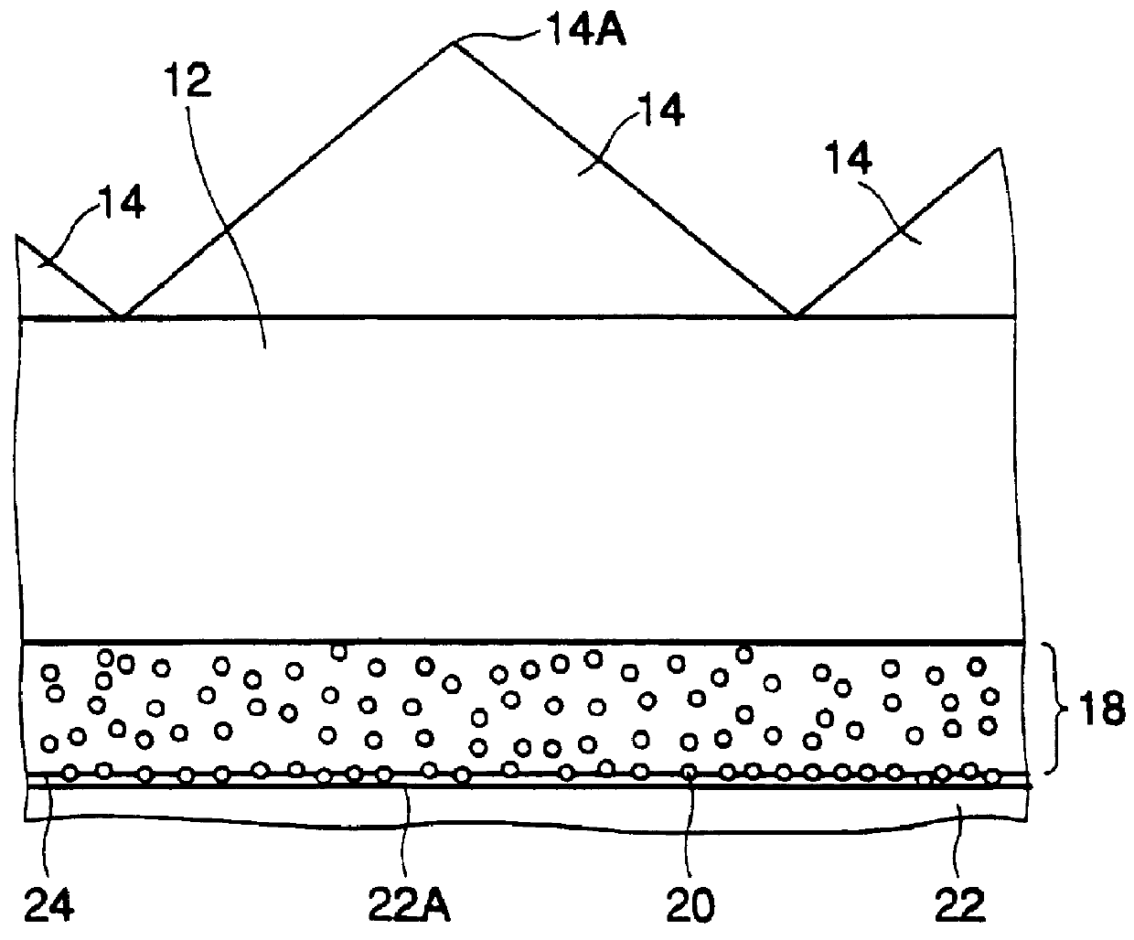
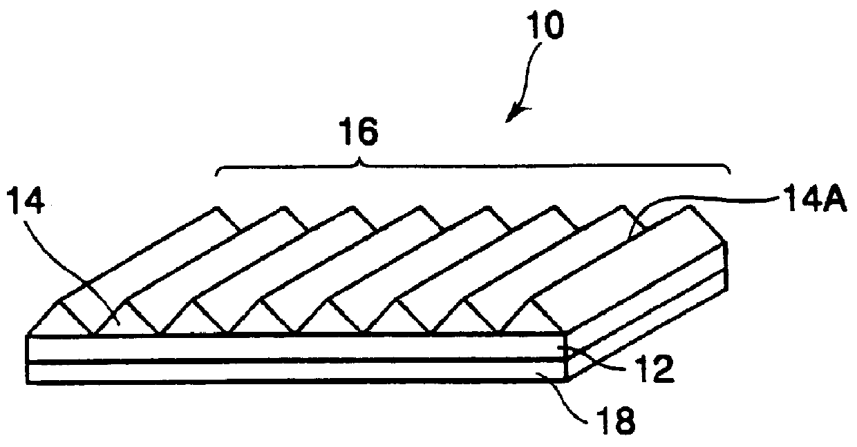
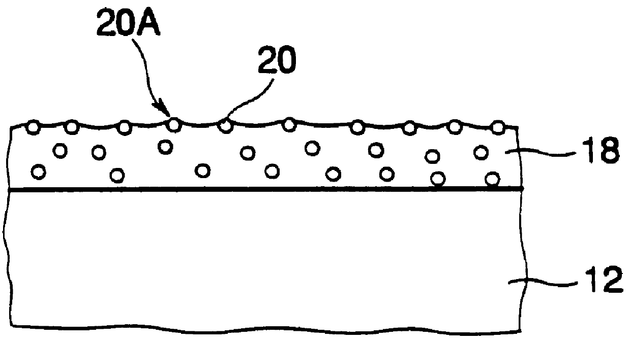
The optical sheet 10 uses an optical sheet which is made by applying a transparent adhesive layer of about 1 .mu.m in thickness onto a transparent biaxially-extended PET film (125 .mu.m in thickness), and applying an ultraviolet-setting resin having as its main ingredient a prepolymer of epoxy acrylate for forming a pattern of unit prisms onto it, and then mold-releasing the coating resin film after it has been hardened and which has unit prisms 14 arranged adjacently to one another so that their ridge-lines 14A are in parallel with one another at intervals of 30 .mu.m, each of said unit prisms being an isosceles having a vertical angle of 85.degree. in section. The spherical beads 20 are disposed in the following manner on the opposite (reverse surface to the prism surface 16 of the transparent base sheet 12 having the unit prisms 14 formed on it.

A coating material composed of light-transmissive beads of a bridge-structured ...


PUM

PropertyMeasurementUnit
particle diametersaaaaaaaaaa
vertical angleaaaaaaaaaa
diametersaaaaaaaaaa

Abstract

In an optical sheet 10 having a prism surface 16 formed by providing unit prisms 14 on the upper surface of a transparent base material 12, a coating layer 18 is provided on the reverse surface of the transparent base material opposite to the prism surface 16, spherical beads 20 are arranged projecting from the surface of the coating layer 18 by 1 to 10 mu m in height, and the coating layer 18 is brought into contact with the flat and smooth surface 22A of the light-transmissive material 22 through the spherical beads 20 which are put between them. The spherical beads are 1 mu m or less in half bandwidth of the distribution of particle diameters and are made uniform in height projecting from the coating layer 18.

Description

1. Field of the InventionThe present invention relates to an optical sheet and an optical sheet lamination ("lamination" includes stacking or putting on in not contact with another) composed of a prism sheet, a lens sheet and / or an optical diffusing sheet suitable for use in a back light surface light source used in illuminating from the back a light-transmissive type display panel of a light-transmissive type liquid crystal display apparatus, an advertising board or the like, and a surface light source device and a light-transmissive type display apparatus using the same optical sheet or optical sheet lamination.2. Prior ArtIn a liquid crystal display apparatus in recent years, according to necessity of reducing of its power consumption and making it thin and light in shape and weight, a surface light source for illuminating the liquid crystal display apparatus from the back has been naturally required also to be made thin and light in shape and weight and has been reduced in power...

Claims


Application Information

Patent Timeline
Patent Type & Authority Patents(United States)
IPC IPC(8): F21V8/00G02B5/04G02B5/02
CPCG02B5/021G02B5/0226G02B5/0231G02B5/0242G02B5/0278G02B5/045G02B6/0031G02B6/0038G02B6/0041G02B6/0043G02B6/0046G02B6/005G02B6/0051G02B6/0053G02B6/0055G02B6/0071G02F1/133606G02B5/0215G02F2001/133607G02F1/133607
Inventor KASHIMA, KEIJIARAKAWA, FUMIHIRO
Owner DAI NIPPON PRINTING CO LTD
Why Eureka
Try Eureka