Fluid filling system with fill time optimization

a filling system and filling technology, applied in liquid handling, packaging goods, transportation and packaging, etc., can solve the problems of limited filling accuracy, unsuitable volumetric filling, and limited filling speed

Inactive Publication Date: 2000-11-21
IDEAL PAK MASSMAN LLC
View PDF20 Cites 27 Cited by
  • Summary
  • Abstract
  • Description
  • Claims
  • Application Information

AI Technical Summary

Benefits of technology

While these hybrid filling schemes address some of the disadvantages of the individual volume-metered, time-metered, and weight-metered filling methods, they can also combine and compound some of their disadvantages. There is thus still a need for a filling method which provides the accuracy of weight-metered filling, while at the same time avoids its implementation costs and undesirably long filling times.
It can be seen that by use of this scheme, as successive containers proceed through the filling stations, t.sub.timed (t) will converge towards t.sub.N (t) (wherein t.sub.N (t) is the filling time at the weight-metering filling station for the present container). Therefore, the time-metered and weight-metered filling stations will each eventually perform filling for the same (or substantially the same) amount of time, and no station will "hold up" the line or sit idle while other stations are operating. Since weight-metered filling is used to top off each container, each container is filled to a desired net weight as accurately as if solely weight-metered filling was used. However, since the container is in large part filled by use of the faster time-metered filling scheme, the invention does not suffer from the slow filling times of weight-metered filling. Additionally, the system's use of only a single weight sensor and feedback system (at the weight-metered filling station) greatly reduces the cost of the system in comparison to systems wherein multiple weight-metered filling stations are used.
It is therefore seen that the invention obtains the accuracy advantages of weight-metered filling and the speed and cost advantages of time-metered filling. More advantageously, because the invention optimizes the filling times between all filling stations, it is found to result in higher productivity than prior systems which combined weight- and time-metered filling. As an example, in the system of Pioch, containers are filled by time-metered filling and then topped off by weight-metered filling, but no attempt is made to relate the time-metered and weight-metered fill times to enhance efficiency. In Pioch, the weight-metered filling time can be said to be dependent on the time-metered filling time (since longer time-metered filling times will result in less weight to be added to completely fill the containers), but the reverse is not strictly true; the time-metering fill time is preset, and is unaffected by the weight-metering fill time. The invention is also fundamentally different from prior systems such as Izzi, Baruffato et al., Townsley, Bohm, McGregor, and Edwards et al. in that the weight filling stations or weight sensors of these prior systems essentially strive for redundancy: once the weight feedback adjusts the filling times / volumes to attain the correct filling weight, the weight sensors are essentially rendered unnecessary--assuming uniformity in the product, containers, and filling apparatus, there is no longer any need for the weight sensors since the desired weight has been attained. In contrast, the present invention fully utilizes a weight filling station to fill each container.

Problems solved by technology

Volumetric filling is subject to the disadvantages that filling accuracy is limited by the accuracy of the control of the chamber volume, and filling speed is limited by the time necessary for refilling the chamber.
Volumetric filling is also unsuitable where one wishes to fill a container with a desired weight of product: variations in product density will lead to variations in the weight of the product dispensed from the chamber and result in different weights being dispensed into different containers; viscous products may stick to the dispensing apparatus and result in incomplete dispensation; and so forth.
However, time-metered filling is subject to inaccuracy unless a constant flow rate is precisely maintained, and this is particularly difficult to attain where flow rates are high.
Additionally, time-metered filling is subject to the same disadvantages as volumetric filling in that variations in product density will result in different weights of product being dispensed to different containers, even if the volume of the dispensed product remains relatively constant from container to container.
First, the weight sensors and feedback apparata are quite costly if any reasonable degree of accuracy is required.
Second, the filling time per container tends to be significantly longer owing to the weight feedback; sensitive weight sensors need time to "settle" prior to giving accurate weight readings, and additionally slower filling rates must often be used since the flow must be cut off precisely at or slightly before the time the desired weight is reached, or overshoot will result in an overweight container with product "give-away".

Method used


Image

  • Fluid filling system with fill time optimization
  • Fluid filling system with fill time optimization

Examples


Embodiment Construction

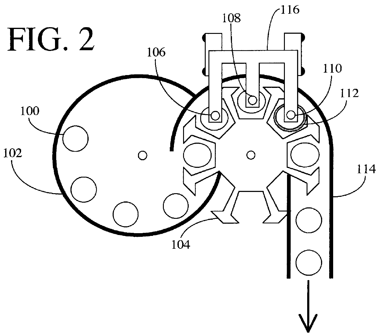
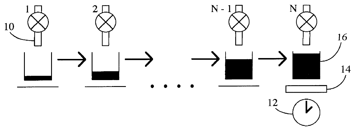
Referring to FIG. 1 of the drawings, an exemplary time-optimized fluid filling system in accordance with the present invention is shown. Assume there are N filling stations, the first N-1 stations (stations 1, 2, . . . N-2, N-1) using time-metered filling and the final station N using weight-metered filling. At each station, a filling nozzle 10 is shown, with the final filling station N also including a timer 12 (e.g., a controller with an incorporated clock) and a weight sensor 14. The total time T to fill a container 16 is

T=t.sub.1 +t.sub.2 + . . . +t.sub.N-1 +t.sub.N

where t.sub.1 represents the time for filling at the first filling station, t.sub.2 is the time for filling at the second filling station, etc.

For the system to achieve the most rapid throughput of containers without a "bottleneck" in the filling process, the ideal case would be

t.sub.1 =t.sub.2 = . . . =t.sub.N-1 =t.sub.N

so that no filling station would "hold up" the line, or conversely no nozzle would sit inactive wh...


PUM

PropertyMeasurementUnit
timeaaaaaaaaaa
weightaaaaaaaaaa
filling timeaaaaaaaaaa

Abstract

A fluid filling system is disclosed wherein containers to be filled with fluid materials are supplied first to one or more time-metered filling stations, and then to a weight-metered filling station. At first, the time-metered filling station(s) is / are inactive, and only the weight-metered filling station is used to fill a first container to a desired final weight. A timer is used to monitor the filling time necessary to reach the desired final weight. When later containers are then supplied to the time-metered filling station(s), they are filled at each time-metered station for a filling time which is dependent on the previously measured filling time for the weight-metered filling station. These containers are then "topped off" by the weight-metered filling station to precisely fill them to the desired final weight, and the time required for such topping off is measured for use in subsequent modification of the filling times at the time-metered filling stations. For each container, the filling time at each time-metered filling station is dependent on the filling time at the weight-metered filling station in such a manner that the two will converge towards each other with successive containers until they are substantially or exactly equal. Preferably, the dependence between the time-metered filling time and weight-metered filling time are such that ttimed(t)=tN(t-1)+Qx[tN(t-1)-ttimed(t-1)]wherein tN(t-1) is the filling time at the weight-metering filling station for a prior container; ttimed(t) is the filling time at the time-metering filling station for the prior container; ttimed(t-1) is the filling time at the time-metering filling station for the prior container; Q is a predetermined real number.

Description

This disclosure concerns an invention relating generally to methods and apparata for fluid dispensation, i.e., the dispensation of liquids and flowing powders or other solids. The invention relates more particularly to methods and apparata which are particularly suitable for use in automatic and semi-automatic container fillers for filling containers with a desired amount of fluid product.The three most common types of fluid filling schemes are volumetric filling, time-metered filling, and weight-metered filling. All are commonly implemented in semi-automatic or automatic filling systems wherein empty containers are presented by conveyors or other transport mechanisms to filling stations. Once the containers reach the filling stations, they are stopped, filled to the desired degree by nozzles or other dispensing apparata, and then released upon completion of the fill.In volumetric filling (also known as volume-metered filling), a set volume of fluid is dispensed into a container: a ...

Claims


Application Information

Patent Timeline
Patent Type & Authority Patents(United States)
IPC IPC(8): B65B3/00B65B3/28B65B3/34
CPCB65B3/34B65B3/28
Inventor BETHKE, STEVEN D.
Owner IDEAL PAK MASSMAN LLC
Why Eureka
Try Eureka