Method, system and apparatus to provide for universal bellhousing between engine and transmission of vehicle

a technology of engine and transmission, applied in mechanical equipment, gearing details, transportation and packaging, etc., can solve the problems of large initial startup cost through mass production, large capital and time commitment to process design, and manufacturer's trade-off of weight versus strength, so as to increase the safety factor of the bellhousing, eliminate residual stress, and increase the safety

Active Publication Date: 2014-01-23
ACCEL PERFORMANCE GRP
View PDF15 Cites 7 Cited by
  • Summary
  • Abstract
  • Description
  • Claims
  • Application Information

AI Technical Summary

Benefits of technology

[0011]A spun bellhousing from a high strength alloy maintains its shape since the spin forming eliminates residual stress associated with tradition pressing methods. The combination of modern alloys and high power spinning machines eliminates the costly development of molds for casting or forms for pressing or hydro forming The finished product is stronger, lighter, and stable than traditional pressed or cast attachments. The process allows short production runs decreasing per unit costs and the benefits of infinite flexibility. Modern spin forming and alloys provide a safer, stronger more stable product with fewer costs than the other processes.
[0013]The process of making such a bellhousing does not require the development of forms, such as those required for hydroforming or pressing, and may be formed from steel plate, thereby increasing the safety factor of the bellhousing. Additionally, a variety of engine and transmission combinations may be used without expensive or weighty adapter plates between the bellhousing and engine or transmission. The spin forming step also eliminates residual stress in the bellhousing, further increasing its safety qualities.

Problems solved by technology

The process requires a large commitment of capital and time designing the molds.
They can only justify the large initial startup costs through the economics of mass production.
The manufacturer is faced with a tradeoff of weight versus strength when selecting either aluminum or steel.
New high torque engines create stresses that cause failure of the traditional cast bellhousing.
This market is not economically viable for traditional mass production methods since the price per piece is not sufficiently off set by production numbers.

Method used


Image

  • Method, system and apparatus to provide for universal bellhousing between engine and transmission of vehicle
  • Method, system and apparatus to provide for universal bellhousing between engine and transmission of vehicle
  • Method, system and apparatus to provide for universal bellhousing between engine and transmission of vehicle

Examples


Embodiment Construction

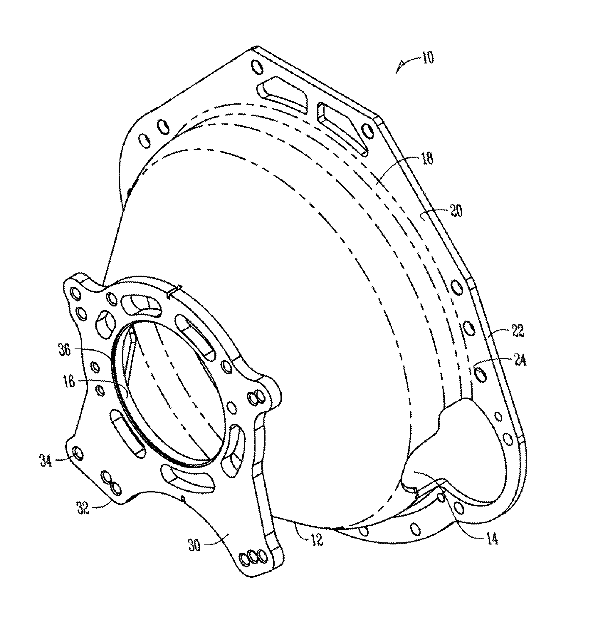
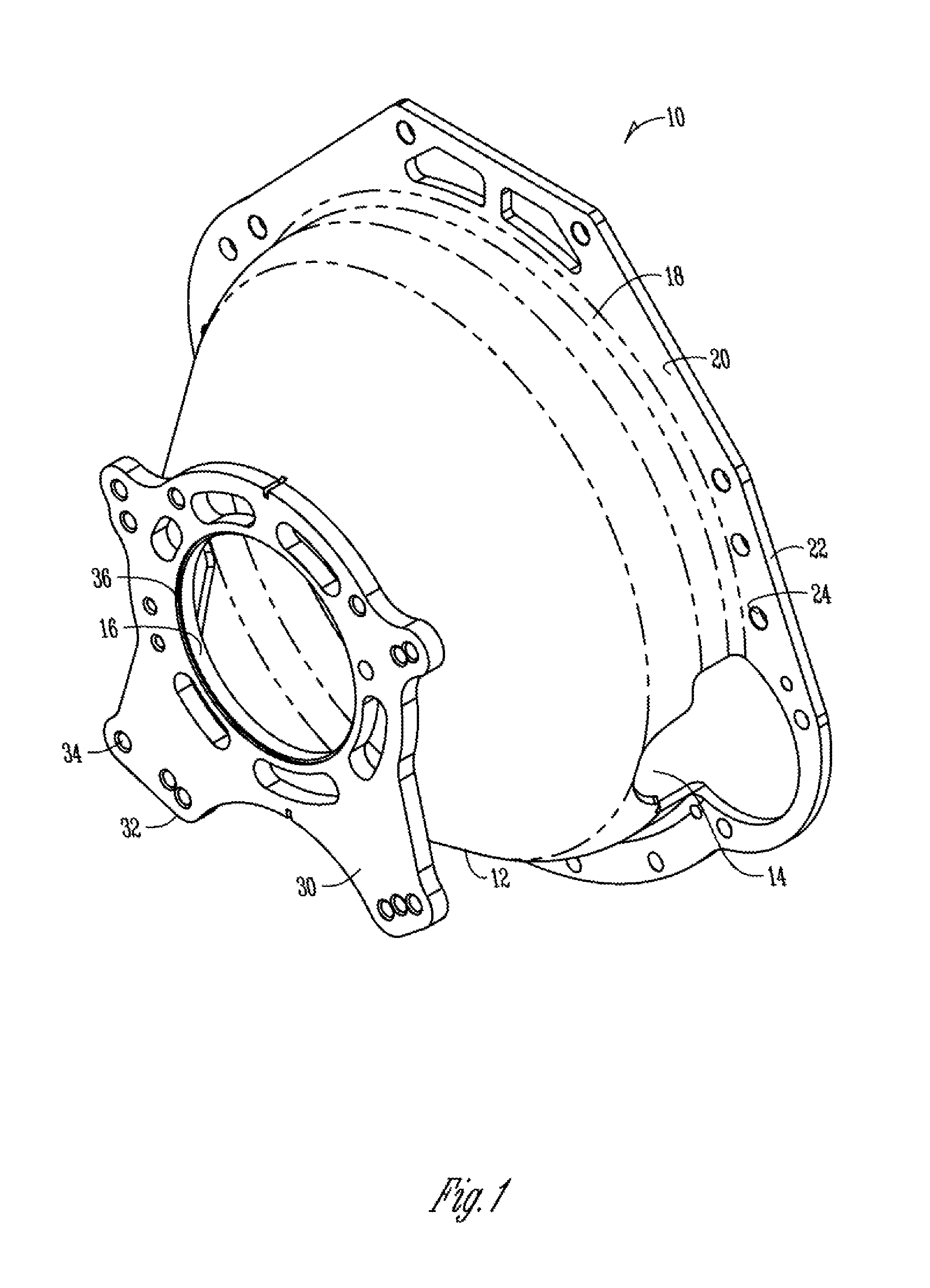
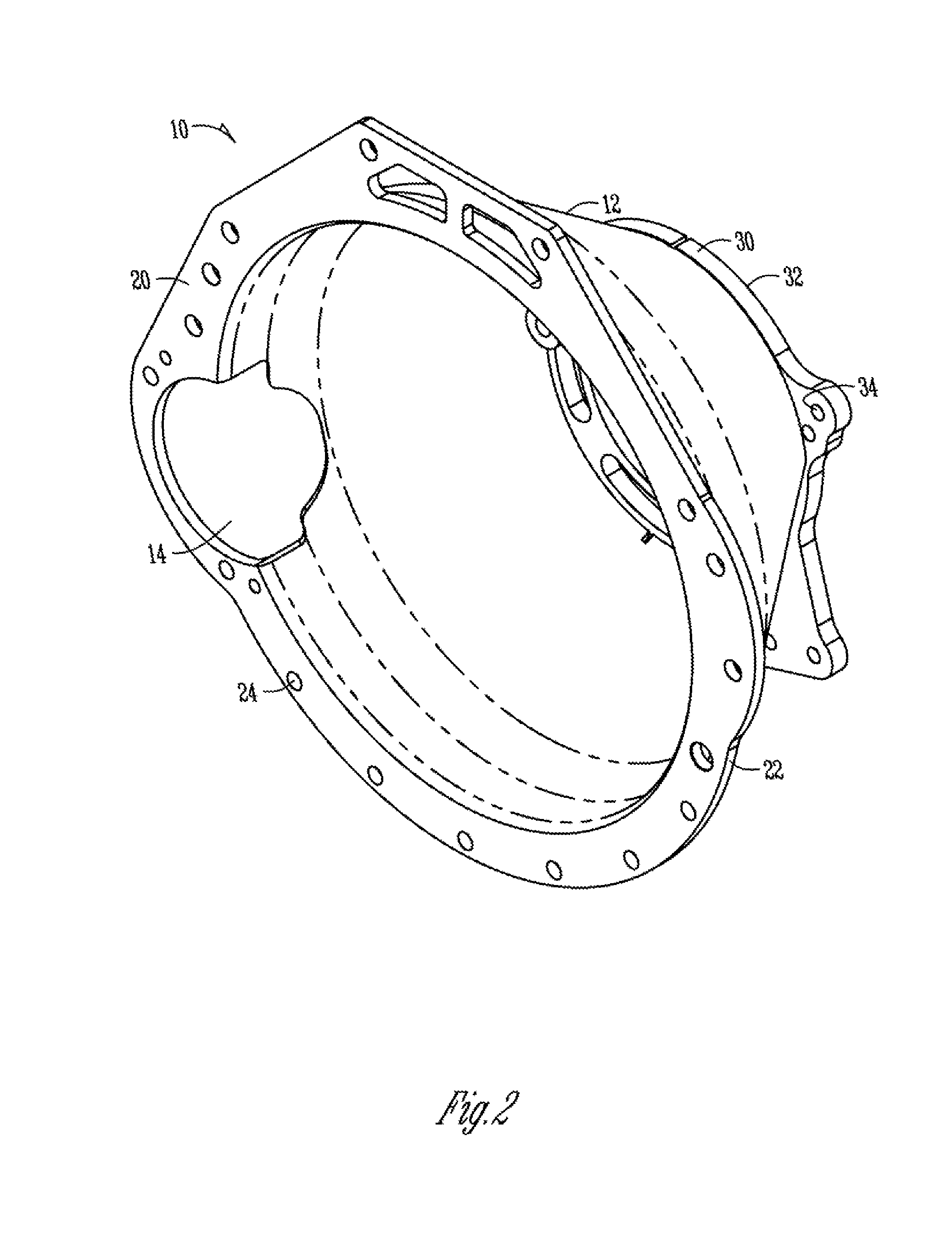
[0021]An embodiment of this invention is a universal bellhousing design and manufacturing process that allows a small number of housing sizes to be configured to mate with a large number of engine and transmission models. This is an important aspect of this invention as each engine and transmission has a unique mounting pattern and size and thus would require separate tooling.

[0022]As shown in FIGS. 1-4, the bellhousing 10 generally comprises a cone 12, a flange 20, and a transmission plate 30. The flange 20 has a hole pattern 24 corresponding to a mating surface on an engine. The transmission plate 30 also has a hole pattern 34 and a profile 32 corresponding to a transmission. The cone 12 also features a number of openings 14 which allow the bellhousing 12 to fit about the engine transmission interface while allowing access for the shifter cable and starter. The arrangement of the openings 14, and the hole pattern 24 on the flange 20 and hole pattern 34 on the transmission plate 30...


PUM

PropertyMeasurementUnit
forceaaaaaaaaaa
transmissionaaaaaaaaaa
rotational torqueaaaaaaaaaa

Abstract

A universal bellhousing which may be adapted to a variety of automotive engine and transmission combinations and method of making the same is disclosed. The bellhousing is made by spin forming a sheet of steel and welding a transmission plate onto the cone. The cone and transmission plate are indexed to mount to a specified engine-transmission combination.

Description

CROSS REFERENCE TO RELATED APPLICATIONS[0001]This application is a divisional of U.S. patent application No. 12 / 258,912 filed on Oct. 27, 2008, which claims priority to U.S. Provisional Application No. 60 / 983,347 filed on Oct. 29, 2007. The disclosure of these applications are hereby incorporated by reference in their entirety.BACKGROUND OF THE INVENTION[0002]Transferring power from a rotating engine or motor to a transmission or other implement requires an attachment mechanism to absorb the rotational torque differential between the engine and the desired transmission or implement. The attachment maintains a specific relationship of the components to prevent unwanted loss of energy from friction associated with misalignment of the rotating shaft from the motor with a transmission or other component. Additional consideration is given for the forces generated from the environment the assembly is to be employed. In an internal combustion engine the area between the engine and the tran...

Claims


Application Information

Patent Timeline
Patent Type & Authority Applications(United States)
IPC IPC(8): F16H57/02
CPCF16H57/02B21D22/16Y10T29/49996Y10T74/2186Y10T29/49231B21D53/88F16H57/025
Inventor MCCOMBS, ROSSGLENN, JOSEPH PATRICK
Owner ACCEL PERFORMANCE GRP
Why Eureka
Try Eureka