


Quick Research
Generate reliable direction feasibility study reports for your R&D in just a few steps.

Technical Q&A
Discover and master advanced knowledge NOW. Basics, ideas, possibilities, all at once.

Find Solutions
As an expert in R&D theories, this can generate solutions to your technical problems instantly.

Evaluate Feasibility
Analyze your overall solution with one click, know your potential R&D risks in advance.

Monitor Landscape
Get weekly tech updates, stay abreast of the latest tech innovations and key insights.
Method for attaching solderable wire leads to a lead frame
- Summary
- Abstract
- Description
- Claims
- Application Information
AI Technical Summary
Benefits of technology
Problems solved by technology
Method used
Image

Examples
Embodiment Construction
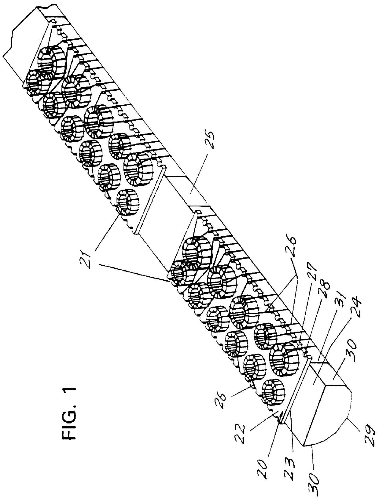
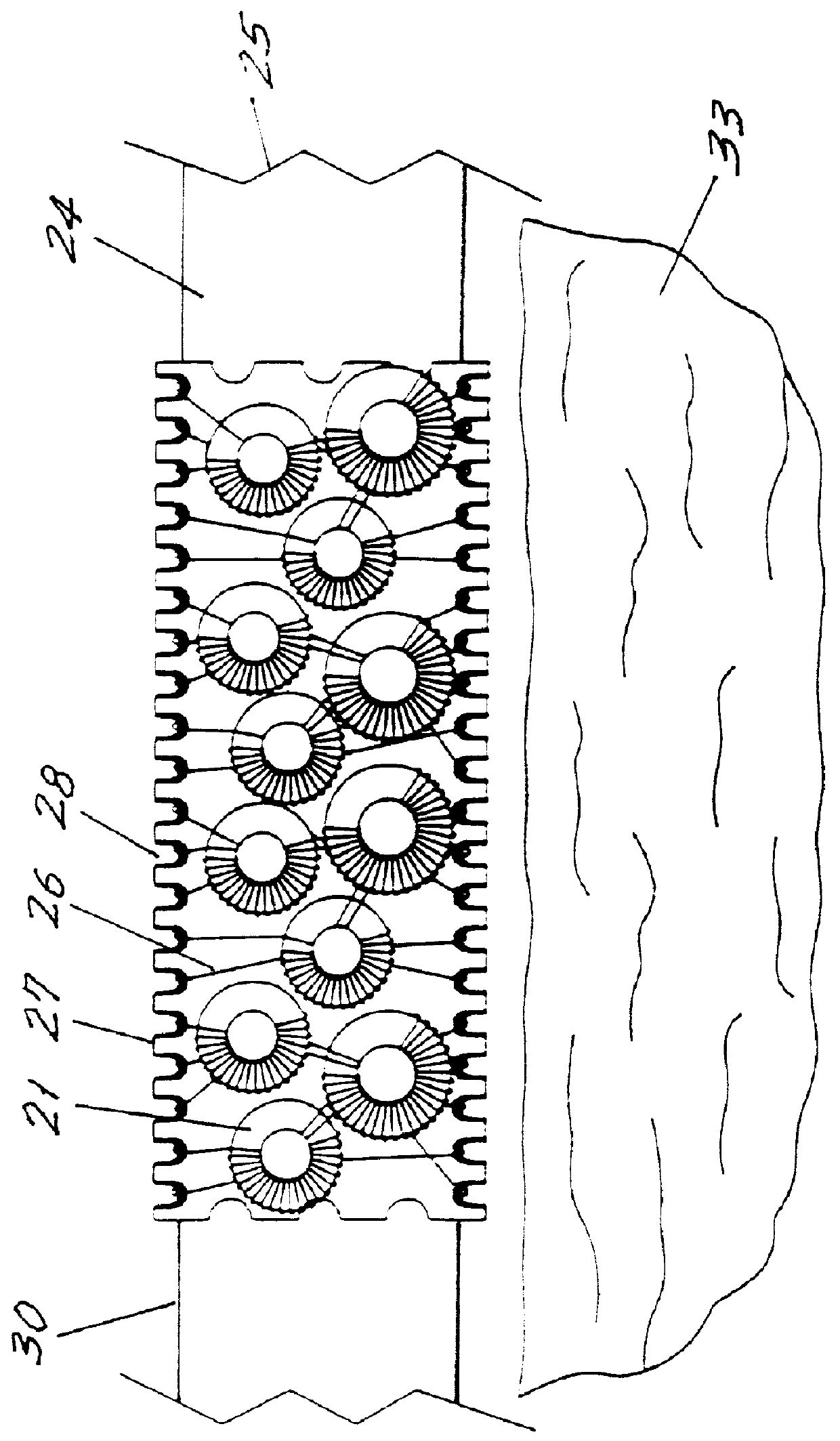
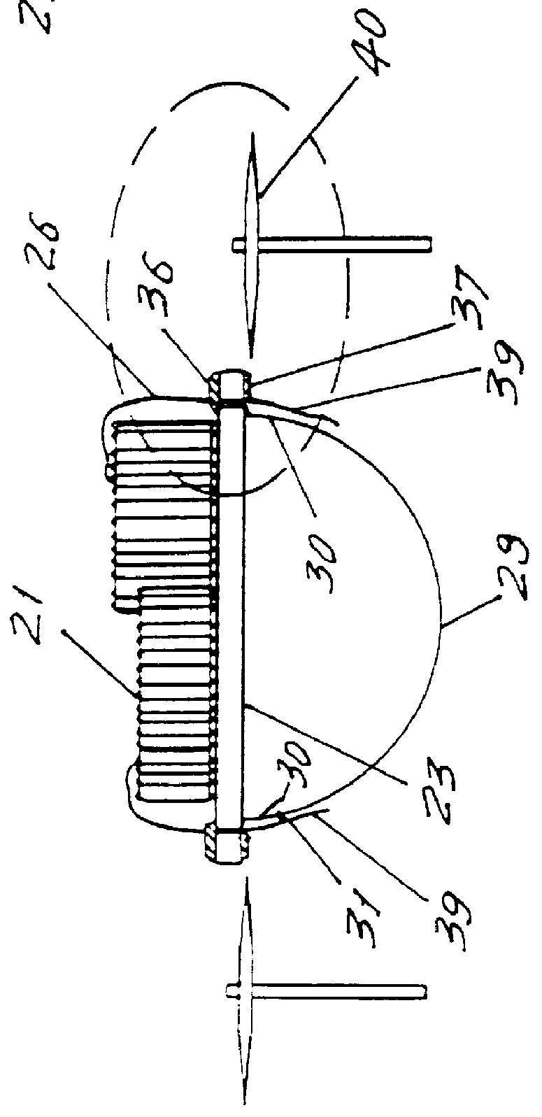
Referring to the drawings, FIG. 1 shows an assembly according to the invention used to perform the method of the invention. A flat PC board 20 of insulating material has a plurality of electronic components, here illustrated as ferrite toroids 21, mounted on the top surface 22 of the PC board 20. The bottom side 23 of the PC board 20 rests on the top surface 24 of a temporary support fixture 25, detailed below. Lead wires and particularly magnet wires 26, are conventionally wound around the toroids 20 and are led to the side edges 27 of the PC board, about where a receiving pin for each wire might be found in the prior art (FIG. 8). Instead, the side edges 27 of the board are provided with respective pathways, in the form of grooves 28 which are half circle shape and preferably metal plated. The wires 26 are led down through their respective grooves.
A temporary support fixture 25 of a material which will not interfere with the solder application step is disposed below the PC board 2...
PUM
| Property | Measurement | Unit |
|---|---|---|
| Thickness | aaaaa | aaaaa |
Abstract
Description
Claims
Application Information
 - R&D Engineer
- R&D Manager
- IP Professional
- Industry Leading Data Capabilities
- Powerful AI technology
- Patent DNA Extraction
Browse by: Latest US Patents, China's latest patents, Technical Efficacy Thesaurus, Application Domain, Technology Topic, Popular Technical Reports.
© 2024 PatSnap. All rights reserved.Legal|Privacy policy|Modern Slavery Act Transparency Statement|Sitemap|About US| Contact US: help@patsnap.com