Valve for the metered introduction of evaporated fuel

a technology of evaporated fuel and valve, which is applied in the field of valves, can solve the problems of high cost and the lik

Inactive Publication Date: 2000-11-21
ROBERT BOSCH GMBH
View PDF9 Cites 27 Cited by
  • Summary
  • Abstract
  • Description
  • Claims
  • Application Information

AI Technical Summary

Problems solved by technology

The problem of a sensitive regulation of the through flow quantity arises since the relatively large entry cross section of the Laval nozzle must always be covered directly by the valve member.
Furthermore, a particular valve stroke of the valve member is required for a particular through flow quantity, but depends on the structural design of the Laval nozzle, particularly the dimensioning of its narrowest cross section, so that an adaptation of the characteristic curve of the valve can only occur by means of a structural change to the Laval nozzle form, which is, however, costly.

Method used


Image

  • Valve for the metered introduction of evaporated fuel
  • Valve for the metered introduction of evaporated fuel
  • Valve for the metered introduction of evaporated fuel

Examples


Embodiment Construction

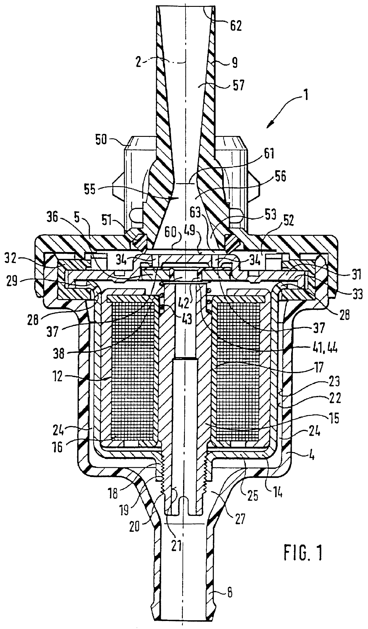
The valve 1 schematically represented in the longitudinal section in FIG. 1 is used for the metered introduction of fuel evaporated from a fuel tank of an internal combustion engine into an intake tube of the engine and is part of a fuel evaporation retention system, not shown in detail, of a mixture-compressing internal combustion engine with externally supplied ignition. The design and the function of this kind of fuel evaporation retention systems can be taken, for example, from the Bosch Technical Instruction, Motormanagement Motronic [Motor Management & Motor Electronics], second edition, August 1993, pp. 48 and 49. The design and function of a valve 1 of this kind, which is also called a regenerating valve or a tank ventilation valve, is furthermore known to one skilled in the art from the German Patent Disclosure 40 23 044, whose disclosure is intended to be a component of the current patent application.

Coaxial to a valve longitudinal axis 2, the valve 1 has a two-part valve ...


PUM


Abstract

PCT No. PCT/DE98/00472 Sec. 371 Date Jan. 25, 1999 Sec. 102(e) Date Jan. 25, 1999 PCT Filed Feb. 18, 1998 PCT Pub. No. WO98/53195 PCT Pub. Date Nov. 26, 1998A fuel tank ventilation valve for a Laval nozzle, which has a sensitive regulation of the through flow quantity. The valve has a valve seat which is embodied on a valve seat body which has at least one opening that can be closed by the valve member. A cross section of the at least one opening is embodied as essentially smaller than an entry cross section of the Laval nozzle that is disposed spaced apart from the valve seat. The valve is suited for a metered introduction of fuel that has evaporated from a fuel tank of a mixture-compressing internal combustion engine with externally supplied ignition into an intake tube of the engine.

Description

PRIOR ARTThe invention is based on a valve for the metered introduction of fuel evaporated from a fuel tank of an internal combustion engine into an intake tube of the engine. A valve of this kind has already been disclosed (DE-PS 42 29 110), which has a valve seat that is formed on an edge of an inlet cross section of a Laval nozzle, which a cylindrical valve member, which can be actuated by an electromagnet, rests against in the closed position. The valve seat consequently also represents an axial boundary of the Laval nozzle. The embodiment of the nozzle as a Laval nozzle makes it possible to achieve a comparatively high through flow speed in order to thus produce only a relatively low flow resistance at a given flow rate of the valve. The problem of a sensitive regulation of the through flow quantity arises since the relatively large entry cross section of the Laval nozzle must always be covered directly by the valve member. Furthermore, a particular valve stroke of the valve me...

Claims


Application Information

Patent Timeline
Patent Type & Authority Patents(United States)
IPC IPC(8): F02M25/08F02M51/00
CPCF02M25/0836F02M25/08
Inventor KRIMMER, ERWINSCHULZ, WOLFGANGMIEHLE, TILMANZIMMERMANN, MANFREDESPERILLA, MARIA
Owner ROBERT BOSCH GMBH
Why Eureka
Try Eureka