Hydraulic mining of tar sand bitumen with aggregate material

a technology of aggregate material and hydrocarbon mining, which is applied in the direction of surface mining, soil shifting machine/dredger, and well accessories. it can solve the problems of ineffective recovery of bitumen from tar sands by conventional well drilling techniques, too viscosity to be produced by conventional methods, and inability to meet the requirements of a large-scale, high-efficiency surface mining

Inactive Publication Date: 2000-11-28
RAAM
View PDF14 Cites 53 Cited by
  • Summary
  • Abstract
  • Description
  • Claims
  • Application Information

AI Technical Summary

Problems solved by technology

However, there are many reservoirs which contain petroleum that is too viscous to be produced by conventional methods.
However, conventional well drilling techniques are ineffective in recovering bitumen from tar sands.
As is well known in the art, there are a host of disadvantages with surface mining methods.
First, surface mining is not economical in many cases.
Furthermore, surface mining creates significant expense associated with reclaiming the mined region and disposing of tailings that result from the processing and extraction of the bitumen.
Unfortunately, most tar sand is at such a depth that it is not economic to remove the tar sand through surface mining.
Most in-situ methods do not pump the slurry material to the surface for processing.
Methods that solely rely on heat to erode the formation and cause the separation of the bitumen are generally regarded as inefficient.
The size of a cavity in which effective bitumen / sand separation can be achieved is limited.
As a result, the cost per unit of the bitumen recovered is very high.
While some of the solvents or chemicals can be recycled and reused, there are additional costs associated with recycling.
Furthermore, recycling is not perfectly efficient as some solvents or chemicals are lost and must be replaced.
As is well known in the art, when an underground cavity is mined there is always a danger that the overburden will collapse into the cavity.
Unfortunately many of these methods require that a gas be introduced into the cavity at sufficient pressure to prevent the overburden from collapsing.
Any time gas is used, there are additional risks and dangers associated with the containment of said gas or the possibility of explosion.
The emitted water causes the erosion of the tar sand formation, causing the sand particles and heavy oil to create a slurry.
However, existing hydraulic methods have many disadvantages similar to those of in-situ methods.
For example, hydraulic methods suffer from the same inefficiencies associated with heating the fluid and using chemical additives.
Hydraulic methods are also inefficient since the slurry material is pumped twice; once to the surface for processing and again back into the cavity when the mining in that cavity is completed.
These inefficiencies make hydraulic mining not only more time consuming but more costly as well.
Also, most hydraulic and in-situ methods rely heavily on high pressure water jets to erode the tar sand formation to separate the bitumen.
Problems of water jet force are compounded as the mining cavity is filled with water.
However, as those in the art can appreciate, this design has many disadvantages namely it is difficult, if not practically impossible, to configure and flex the tube once it is in a formation.
This method is difficult to implement and inefficient.

Method used


Image

  • Hydraulic mining of tar sand bitumen with aggregate material
  • Hydraulic mining of tar sand bitumen with aggregate material
  • Hydraulic mining of tar sand bitumen with aggregate material

Examples


Embodiment Construction

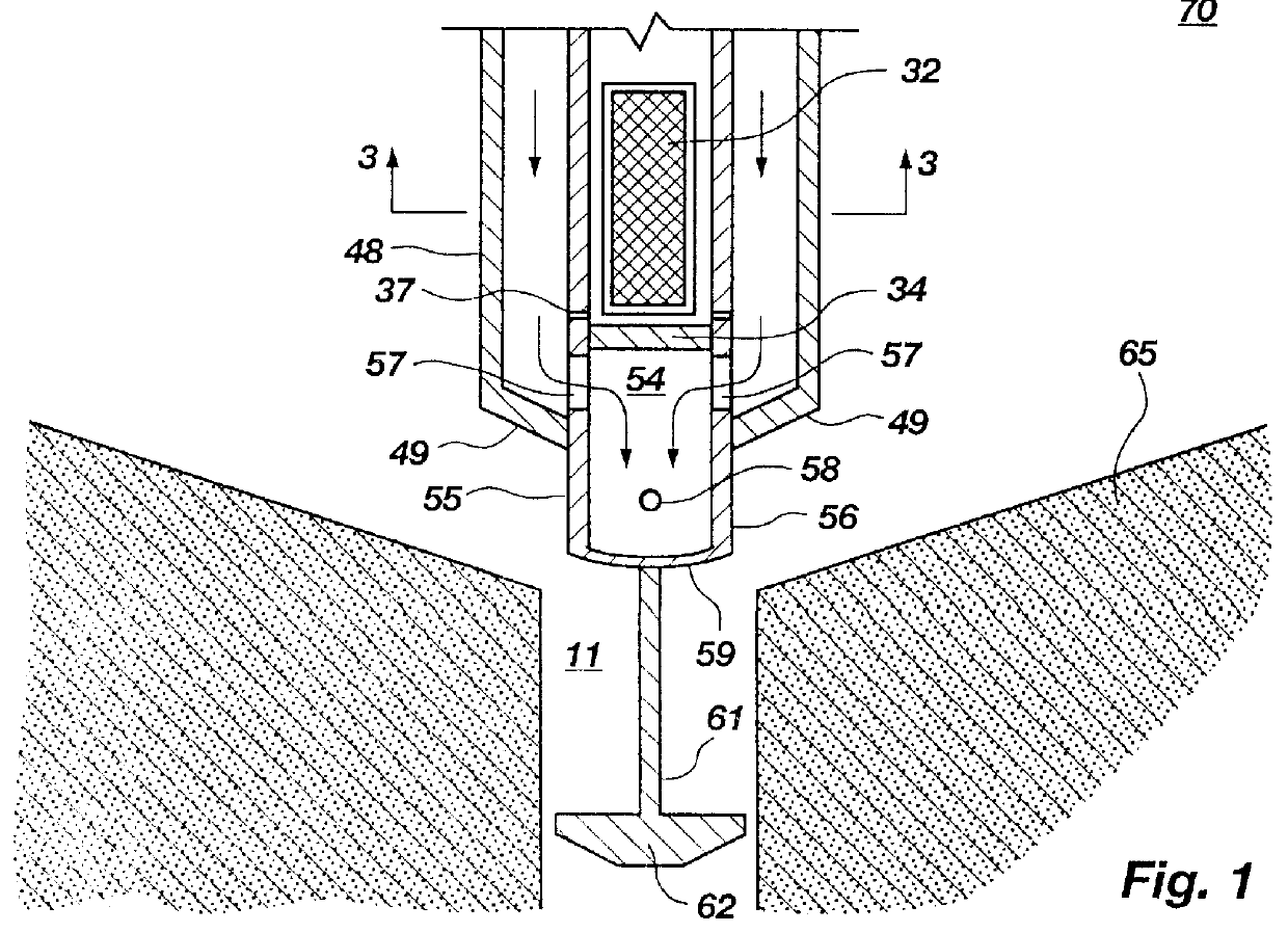
The following description is representative of the process of the present invention in the hydraulic mining of tar sand and recovery of bitumen from a single cavity.

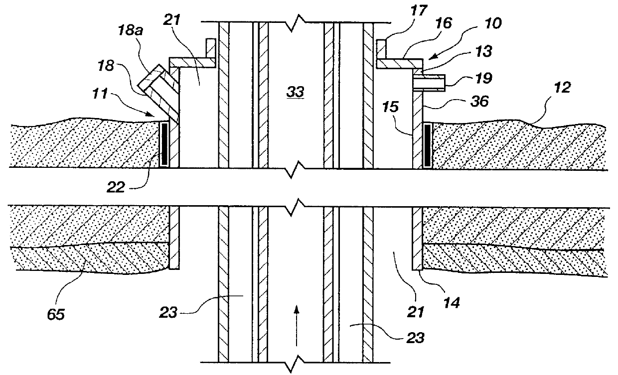
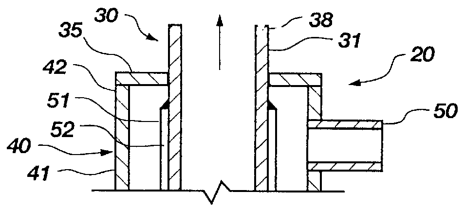
A borehole 11 is drilled through the overburden 12 and extends into a tar sand deposit 65 in the manner described above. Into the borehole 11 is inserted a casing 10 which is cemented in place by a seal 22. A mining tool 20, as described above, is then passed through the casing and into the tar sand deposit with the drill hole plug 62 positioned in the borehole 11 below the mining tool 20 as described.

The deposit is a tar sand having an ambient temperature of about 50.degree. F. comprising about 11.7% by weight bitumen in a sand base having a screen size distribution as follows:

The process, as described, is based on the mining of 77,000 lbs / hr of a tar sand comprising 9,000 lb / s hour bitumen (specific gravity .sup..about. 1 gm / cm.sup.3) and 68,000 lbs / hr of sand as described.

The process is started by charging the borehol...


PUM


Abstract

A method and apparatus for the hydraulic removal of bitumen from a tar sand deposit comprises forming a borehole into the tar sand deposit and securing a casing into the borehole. Into the casing is inserted a mining tool having a water/diluent channel and a slurry exit channel. Through the casing the borehole is charged with crushed aggregate. At the lower end of the tool are nozzles through which high pressure hot water/diluent is injected as a jet from the water/diluent channel into the tar sand deposit causing a cavity to form in the tar sand deposit. The heat of the water/diluent jets and dissolving action of the diluent softens the tar sand contacted and the impact of the jets and the scouring action of the aggregate, as impinged upon by the jets, removes the tar sand from the surface of the developing cavity into a water phase. A bitumen/diluent phase rises to the surface of the water phase and is removed from the cavity through the casing. A water sand slurry at the bottom of the developing cavity is removed from the slurry exit channel where sand is subsequently removed and the water is recovered and reintroduced back into the process along with makeup water and diluent. Water temperature and pressures are controlled to optimize the hydraulic mining process.

Description

BACKGROUND OF THE INVENTION 1. THE FIELD OF THE INVENTION.The present invention relates generally to the mining of petroleum hydrocarbons from petroleum bearing formations. More particularly, this invention concerns the hydraulic mining of bitumen from tar sand formations that are either found too deep or of insufficient thickness to be mined economically by surface mining techniques. 2. The Background Art.Petroleum is generally recovered by penetrating reservoirs with wells. When a well is drilled, the petroleum either flows to the surface by means of natural pressure or by pumping. However, there are many reservoirs which contain petroleum that is too viscous to be produced by conventional methods. Under these circumstances, different methods of extraction must be used.One of the most viscous petroleum deposits is in tar sand deposits that are commonly found in the Western United States, Western Canada and Venezuela. These tar sand deposits contain significant amounts of bituminou...

Claims


Application Information

Patent Timeline
Patent Type & Authority Patents(United States)
IPC IPC(8): E21C25/60E21C25/00E21B43/29E21B43/00E21B41/00
CPCE21B41/0078E21C25/60E21B43/29
Inventor MINDEN, CARL S.
Owner RAAM
Why Eureka
Try Eureka