Eureka AIR delivers breakthrough ideas for toughest innovation challenges, trusted by R&D personnel around the world.

Microwave oven with a grilling device

Inactive Publication Date: 2000-11-28
WHIRLPOOL CORP
View PDF11 Cites 6 Cited by
  • Summary
  • Abstract
  • Description
  • Claims
  • Application Information

AI Technical Summary

Benefits of technology

The object of the present invention is to provide a method and a device which make the manufacture of the grill bulge and the grill elements including their connections to feeders considerably simpler and less expensive and improve the efficiency of the grill. In addition, one object of the method and the device according to the present invention is to increase the technical life of the grill elements.
In addition, it is possible to design the grate in such a way that it exhibits a large surface for IR rays which are directed forwards towards the oven door and a small surface for IR rays which are directed towards the foodstuff which they are intended to grill, which ensures that as little grill capacity as possible is lost at the same time as the oven door is irradiated to the least extent possible in order to prevent it from becoming excessively hot.

Problems solved by technology

However, this results in new problems since a route must be created for the IR rays into the oven cavity, which route leads to the creation of an opening in the cavity wall through which microwaves pass into the grill bulge, from where the microwaves can leak out into the surrounding room.
Even though this shield shields off some of the microwaves, the resulting field in the grill bulge is still relatively strong, which causes problems with radiation leakage to the surrounding room.
A special difficulty in this context are the electric connections of the grill elements, which connections function as antennae for the microwaves.

Method used


Image

  • Microwave oven with a grilling device
  • Microwave oven with a grilling device
  • Microwave oven with a grilling device

Examples


Embodiment Construction

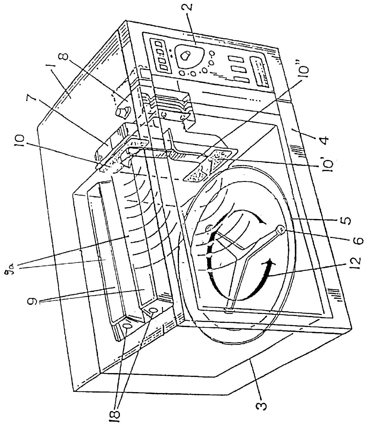
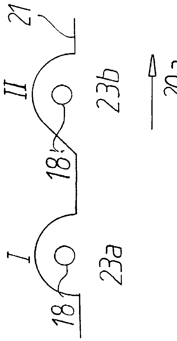
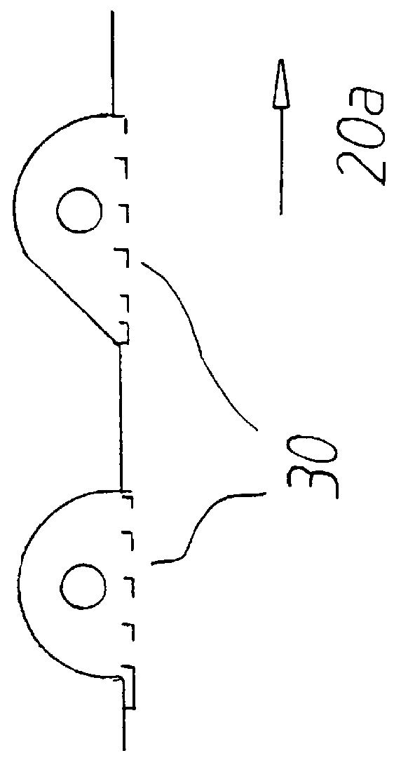
FIG. 1 shows a microwave oven according to the present invention. The oven comprises a casing 1, a control panel 2, a cavity 3 which is arranged in the casing and in which foodstuff is placed during the cooking process, and a door 4 for closing the cavity during cooking. Adjacent to the bottom of the cavity there is a rotating bottom plate 5 with an associated movement mechanism 6, which makes the plate with the food placed on it rotate in the direction of the arrow 12 during cooking. The bottom plate and the movement mechanism can be of a type which is easy to remove when a stationary load is desired. The figure also shows microwave-feeding means 7 and a microwave source 8 for generation of the microwaves. By the intermediary of the feeding means 7 the microwaves are fed through two feeder openings 10 and 10' arranged in one of the side walls of the cavity adjacent to the ceiling and the bottom of the cavity, respectively. In the ceiling of the cavity 3 two reflectors I and II (sho...


PUM


Abstract

PCT No. PCT / EP98 / 00280 Sec. 371 Date Sep. 24, 1999 Sec. 102(e) Date Sep. 24, 1999 PCT Filed Jan. 20, 1998 PCT Pub. No. WO98 / 34436 PCT Pub. Date Aug. 6, 1998A microwave oven with an oven capacity (3) which is designed so that a part (9) of the cavity is essentially free of microwave radiation, in which part (9) is arranged a grill element which radiated IR radiation. The microwave-free space is obtained by a special dimensioning of the connection opening between the actual oven cavity, in which foodstuffs are heated by means of microwave radiation, and the microwave-free space (9).

Description

The present invention relates to a method and a device for IR irradiation of foodstuffs in a microwave oven. In particular, the present invention relates to a device and a method for the arrangement of IR radiating elements in a microwave oven.TECHNICAL BACKGROUND AND PRIOR ARTAt the present time, there are known microwave ovens which comprise grill elements, i.e. means for irradiation of foodstuffs which are to be cooked in the oven with IR radiation, in order to create a grilled texture of said foodstuffs.The conventional method is to arrange grill elements outside the oven cavity, in a so-called grill bulge, in order to avoid creating serious disturbances of the microwave pattern in the oven cavity. However, this results in new problems since a route must be created for the IR rays into the oven cavity, which route leads to the creation of an opening in the cavity wall through which microwaves pass into the grill bulge, from where the microwaves can leak out into the surrounding ...

Claims


Application Information

Patent Timeline
IPC IPC(8): H05B6/80F24C7/02H05B11/00H05B6/76
CPCH05B6/766H05B6/6482H05B6/80
Inventor ANDERSSON, ANN-MARIEGUNNAR, NYREN
Owner WHIRLPOOL CORP
Why Eureka
Eureka Blog
Learn More