Magnetic suspension system

a magnetic suspension and system technology, applied in the direction of bearings, electrical equipment, relays, etc., can solve the problems of increasing the resistance of the suspended object, reducing the diameter of the wire, and using a considerable amount of current to suspend the obj

Inactive Publication Date: 2000-11-28
MAGNETIC PATENT HLDG
View PDF22 Cites 40 Cited by
  • Summary
  • Abstract
  • Description
  • Claims
  • Application Information

AI Technical Summary

Problems solved by technology

A disadvantage of the Fremerey system is that it uses a considerable amount of current to suspend the object at the predetermined position.
Furthermore, the suspended object will be irrecoverably pulled into contact with the support structure by the attractive force between the permanent magnets, when the object moves too close to the support structure.
However, reducing the diameter of the wire substantially increases its resistance and hence the drive voltage required to pass the same current through the coil.
This change in the incident magnetic field on the detector fools the control means into thinking that the object has moved away from the predetermined position at which it is being held.

Method used


Image

  • Magnetic suspension system
  • Magnetic suspension system
  • Magnetic suspension system

Examples


Embodiment Construction

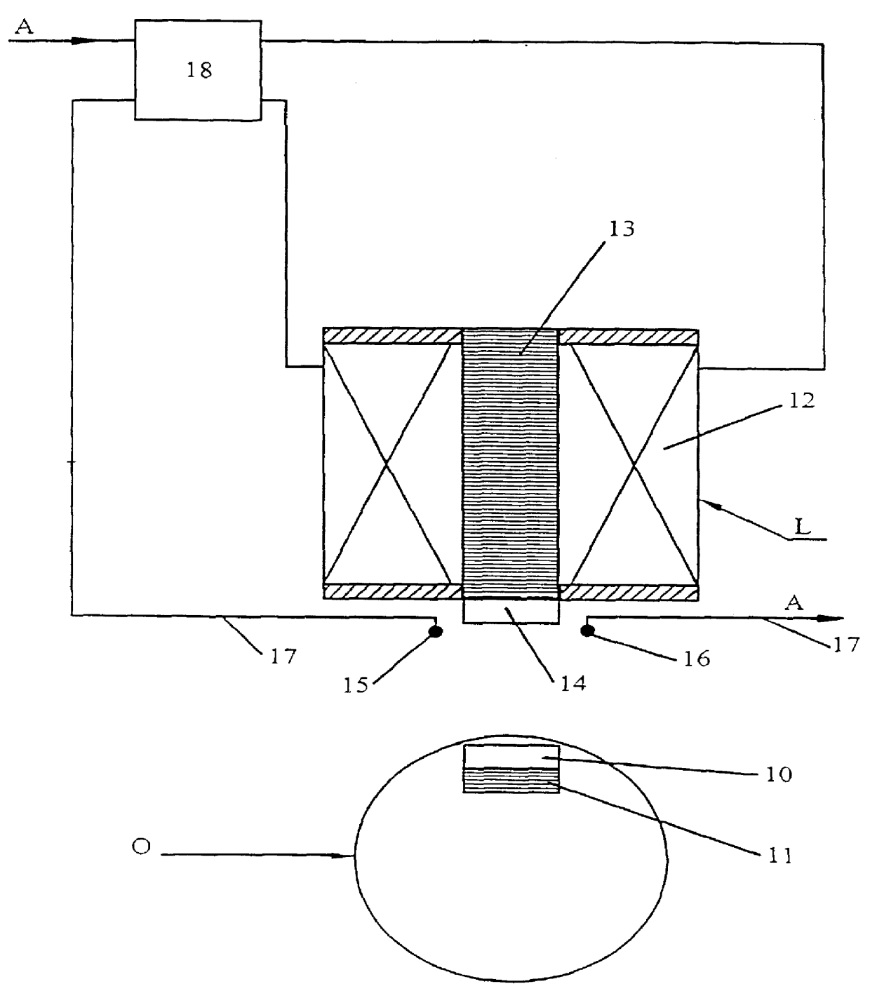
Referring to FIG. 1 of the drawings, there is shown a magnetic suspension system for suspending an object O at a controlled position relative to a fixed structure. The object O is provided with a rare earth permanent magnet 10 mounted to a piece of mild steel 11 which acts as a flux concentrator. An electromagnet 12 is mounted to the fixed structure. In use the object O is magnetically suspended below the electromagnet 12, which comprises a coil L wound on a bobbin: in the example shown the coil L has its axis vertical, but it may be inclined to the horizontal or even be close to the horizontal. The electromagnet 12 has a core 13 of mild steel or other magnetically permeable material, and may rest on a panel having a central aperture aligned with the core of the electromagnet. Further, a second rare earth permanent magnet 14 is mounted to the bottom end of the core 13, to attract the permanent magnet 10 of the object O. The core 13 may be made in two parts with the magnet 14 positio...


PUM


Abstract

A suspension system for magnetically suspending an object O comprises an electromagnetic coil L having an axially extending core 13 of magnetically permeable material and a permanent magnet 14 disposed on its axis. A permanent magnet 10 is also provided in the object O and is arranged such that it is in attraction with the permanent magnet 14 on the coil L, and with the magnetically permeable core 13 so that the object O is suspended at a position below the coil L by the attractive force. Sensors 15,16 on the coil L detect the magnetic field of the permanent magnet 10 in the object O, and provide signals to a control circuit, which applies current to the coil L to attract the object O when the detected field is below a predetermined limit and to repel the object when the detector field is above a predetermined limit. In this manner, the object O is held in position using a relatively low current, since the coil L is only energised when the object moves away from the position in which it is held by the field of the permanent magnets 10,14.

Description

1. Field of the InventionThis invention relates to a system for the magnetic suspension of objects.2. Description of the Prior ArtDE-42-10-741 (Fremerey) discloses a magnetic suspension system comprising an electromagnet and a first permanent magnet mounted to a fixed or movable support structure, an object provided with a second permanent magnet and arranged for suspension at a position below the electromagnet, by an attractive force developed between the two permanent magnets, detector means mounted in a fixed position to detect the magnetic field of the second permanent magnet, and control means for supplying an electrical current to the electromagnet when the magnetic field detected by the detector means changes from the field which is detected when the object is at the predetermined position, the electrical current being varied in accordance with an output signal of the detector means to maintain said object in a predetermined position relative to the electromagnet.A disadvanta...

Claims


Application Information

Patent Timeline
Patent Type & Authority Patents(United States)
IPC IPC(8): F16C39/06F16C39/00B25J15/06
CPCF16C32/0459F16C32/0451
Inventor BOWERS, EDWARD NORMANJONES, RONALD BARRY THOMASSHIRAZEE, NABEEL
Owner MAGNETIC PATENT HLDG
Why Eureka
Try Eureka