Dual media vacuum filter bag

a vacuum filter bag and media technology, applied in the direction of filtration separation, separation process, pedestrian/occupant safety arrangement, etc., can solve the problems of affecting the shock loading efficiency of the bag, releasing a significant amount of respirable particulate materials, and significant health concerns for people with allergies

Inactive Publication Date: 2000-12-05
3M INNOVATIVE PROPERTIES CO
View PDF27 Cites 109 Cited by
  • Summary
  • Abstract
  • Description
  • Claims
  • Application Information

AI Technical Summary

Problems solved by technology

However, relatively recently it has become clear that these bags discharge a significant amount of respirable particulate materials, specifically particles having a diameter of less than 10 microns.
As such these fine respirable particles are placed into the indoor atmosphere by the vacuum cleaner causing significant health concerns for people with allergies and the like.
If the permeability is more than about 1000 m.sup.3 / min / m.sup.2, the diffusion layer is too open to act as an initial barrier to the high velocity particles entering the bag, which adversely affects the shock loading efficiency of the bag.

Method used


Image

  • Dual media vacuum filter bag
  • Dual media vacuum filter bag
  • Dual media vacuum filter bag

Examples


example 1

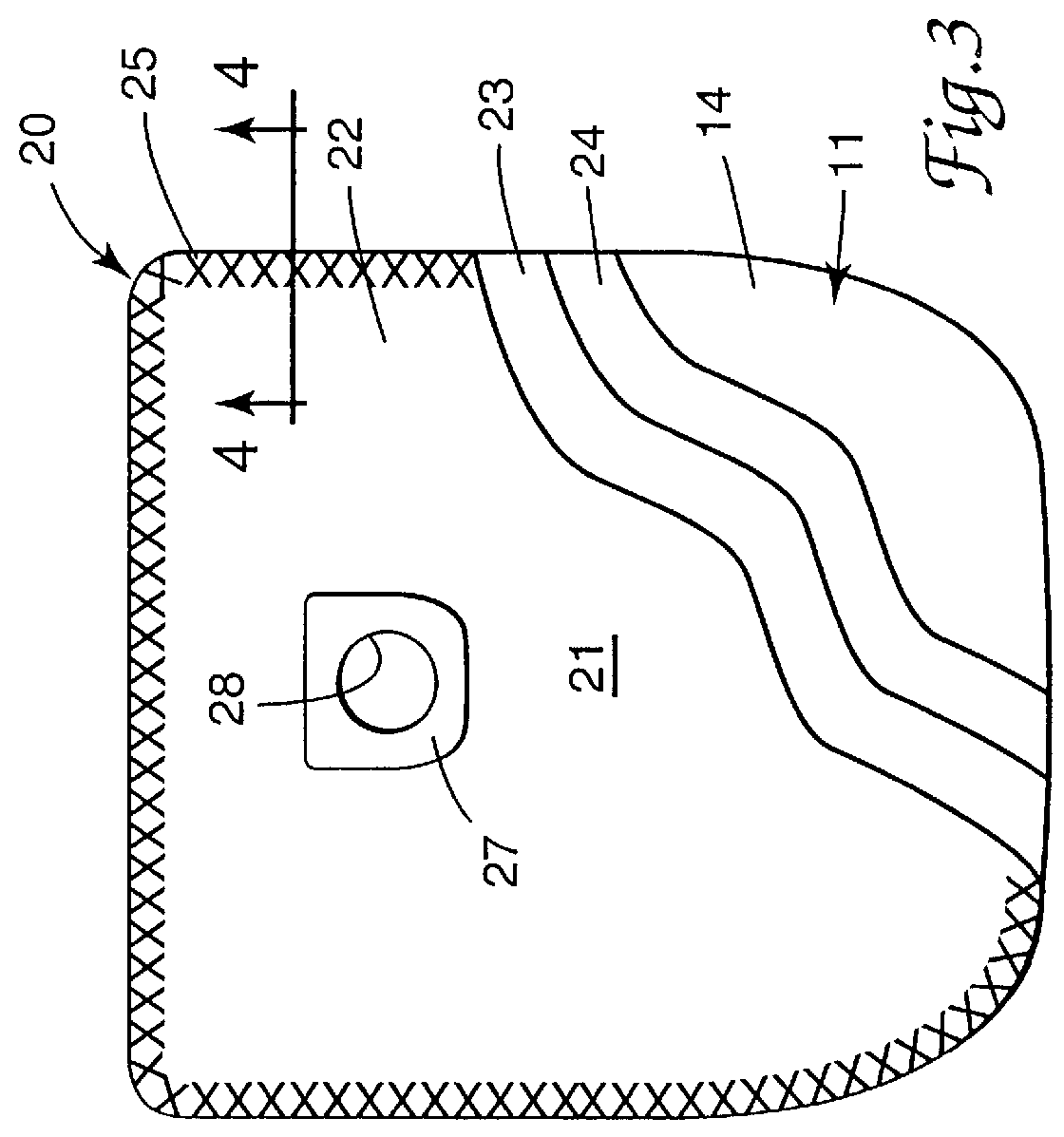
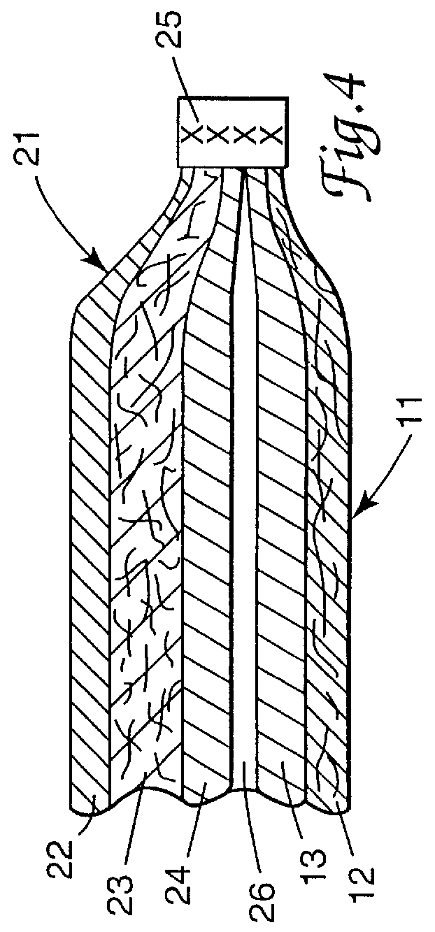
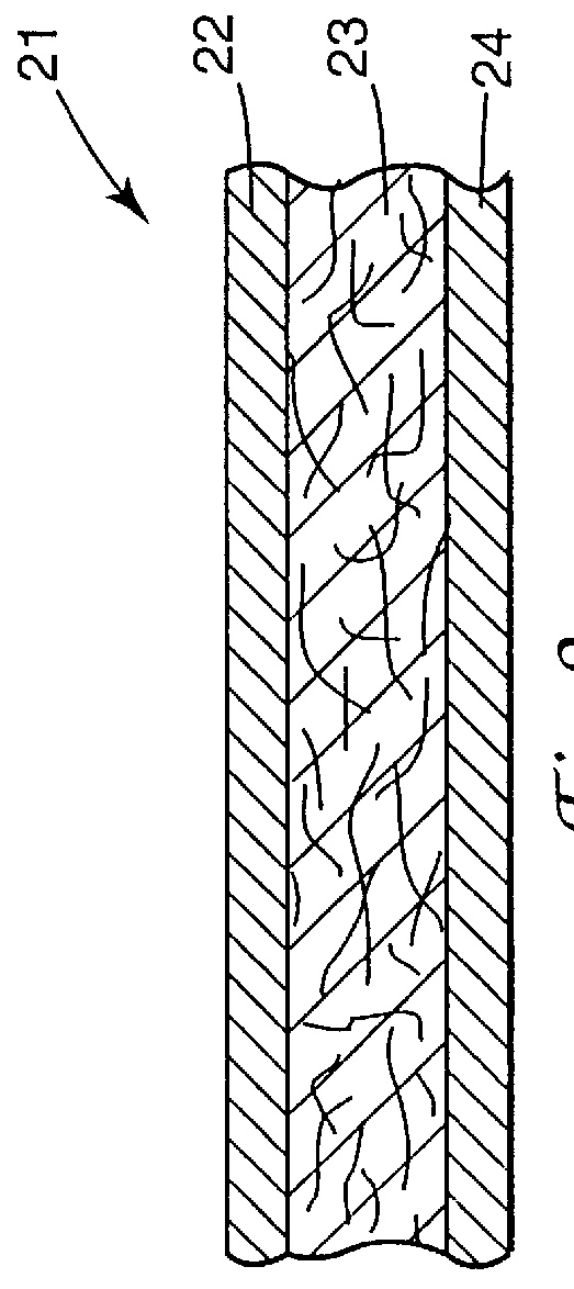
A circular aperture (4.8 cm in diameter was cut into a rectangular piece (45.7 cm.times.25.4 cm) of Media C, centrally positioned width wise and approximately 33.5 cm from one end of the filter media and a cardboard collar adhesively attached to one of the spunbond layers using a Jet Melt 3748 Q hot melt adhesive (available from 3M Company, St Paul, Minn.). The bag was assembled by preparing a laminate consisting of a rectangular piece of spunbond fabric (45.7 cm.times.25.4 cm, 34 g / m.sup.2, available from Fiberweb North American, Inc.), a rectangular piece of polypropylene film (45.7 cm.times.25.4 cm, 65 .mu.m thick, available from American Profol Inc., Cedar Rapids, Iowa ) and finally the collar bearing rectangular piece of Media C, positioned with the collar on the outer face of the filter media, and ultrasonically welding the perimeter of the laminate assembly together using a Branson FS 90 Ultrasonic Welding unit (available from Branson Ultrasonic Corp., Danbury, Conn.) operati...

example 2

The vacuum filter bag of Example 2 was assembled substantially as the bag for Example 1 except that Media C was replaced by Media D.

The emission tests were performed by installing a residential vacuum cleaner Kenmore Progressive Upright in a test chamber, feeding PTI Fine dust (2 g) into the vacuum, and measuring the particulate emission in the exhaust of the vacuum using a LASAIR Model 1002 particle counter (available from Particle Measurement Systems, Inc, Boulder Colo.). Particle emission data are presented in Table 2.

The data in Table 2 clearly demonstrates the effectiveness of the dual media bags of Example 1 and 2 in removing micro-particles. The bags of Examples 1 and 2 were one to two orders of magnitude, respectively, more efficient than conventional cellulose (C1) or hybrid cellulose / meltblown (C2) bag constructions in removing particles. The bag of Example 1 performed substantially comparable to a commercially available electret charged microfiber bag (C3), and both dual ...

example 3

The bag of Example 3 was assembled substantially the same as the bag of Example 1 except that the spunbond fabric used for the inner diffusion layer filter had a basis weight of 17 g / m.sup.2 (available from Fiberweb North American, Inc.) in place of the 34 g / m.sup.2 basis weight fabric.


PUM

PropertyMeasurementUnit
diameteraaaaaaaaaa
weight percentaaaaaaaaaa
diameteraaaaaaaaaa

Abstract

There is provided a vacuum cleaner filer bag including at least two sidewalls which sidewalls are joined by seams. At least one first sidewall comprises a film laminate of a heat sealable film layer and a film support layer. At least one second sidewall comprises a filter laminate comprising at least a synthetic fiber filter layer and synthetic fiber support layer where the at least one first sidewall is joined to adjacent sidewalls by thermal seams. The filter layer is preferably a high efficiency microfiber filter media which provides HEPA level performance for the vacuum cleaner bag.

Description

BACKGROUND AND FIELD OF THE INVENTIONThe present invention relates to vacuum cleaner bags, particularly vacuum cleaner bags having filtration layers.Traditionally, vacuum cleaner bags were constructed with cellulosic paper, generally relatively high basis weight paper. These paper bags are advantageous in terms of their cost. However, relatively recently it has become clear that these bags discharge a significant amount of respirable particulate materials, specifically particles having a diameter of less than 10 microns. These size particles remain airborne for long periods of time and contain many allergens. As such these fine respirable particles are placed into the indoor atmosphere by the vacuum cleaner causing significant health concerns for people with allergies and the like. To address these concerns a number of patents suggest laminating cellulosic bags with inner filtration layers, specifically fine particle synthetic fiber filter material layers, such as meltblown nonwoven...

Claims


Application Information

Patent Timeline
Patent Type & Authority Patents(United States)
IPC IPC(8): A47L9/14B01D39/16B01D39/14
CPCA47L9/14B01D39/1623Y10T428/1362Y10S55/39Y10S55/02B01D39/16
Inventor ZHANG, ZHIQUN
Owner 3M INNOVATIVE PROPERTIES CO
Why Eureka
Try Eureka