Low profile antenna

a low-profile, antenna technology, applied in the direction of resonant antennas, antenna earthings, elongated active element feeds, etc., can solve the problems of difficult to adapt the feed geometry for mobile radio applications, various manufacturing and fabrication difficulties, and the edge feeding arrangement does not lend itself as readily to flush mounting, so as to improve the tuning capability, improve the transmission characteristics, and improve the radiation characteristics

Inactive Publication Date: 2000-12-05
LAIRD CONNECTIVITY INC
View PDF10 Cites 78 Cited by
  • Summary
  • Abstract
  • Description
  • Claims
  • Application Information

AI Technical Summary

Benefits of technology

It is yet another object of the present invention to combine such superior radiation characteristics and improved tuning capabilities with an antenna having seven percent (7%) to ten percent (10%) bandwidth required for mobile or cellular telephone operation.
It is a further object of the present invention to...

Problems solved by technology

2) a feed geometry that is difficult to adapt for mobile radio applications where the antenna must be mounted to the vehicle with a standardized connector system;
4) various manufacturing and fabrication difficulties.
The edge feeding arrangement does not lend itself as readily to flush mounting as a center feed does.
One commercial version of this antenna has the further disadv...

Method used


Image

  • Low profile antenna
  • Low profile antenna
  • Low profile antenna

Examples


Embodiment Construction

)

The detailed description set forth below in connection with the appended drawings is intended as a description of presently preferred embodiments of the invention and is not intended to represent the only forms in which the present invention may be constructed and / or utilized. The description sets forth the functions and the sequence of steps for constructing and operating the invention in connection with the illustrated embodiments. However, it is to be understood that the same or equivalent functions and sequence may be accomplished by different embodiments that are also intended to be encompassed within the spirit and scope of the invention.

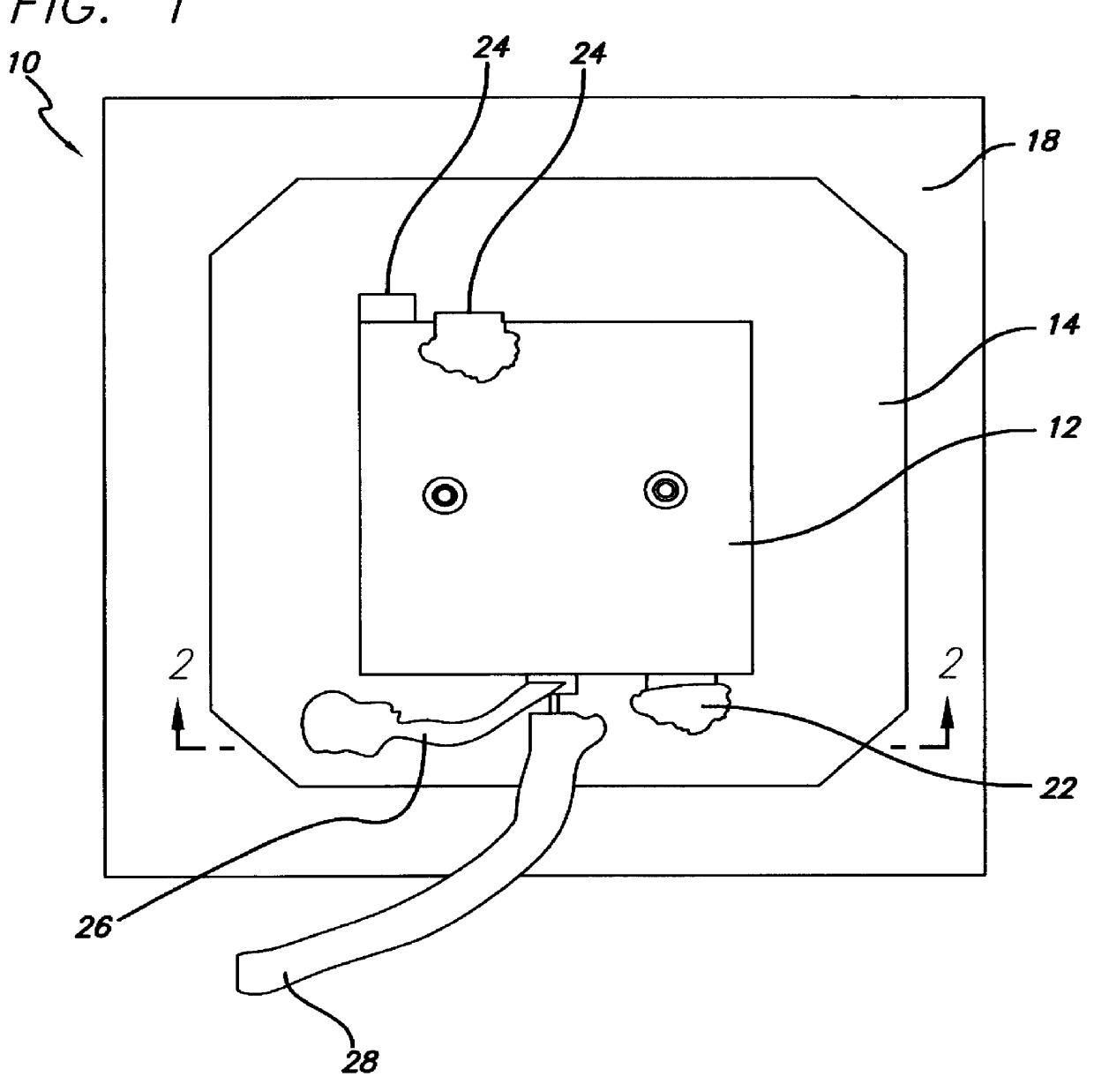
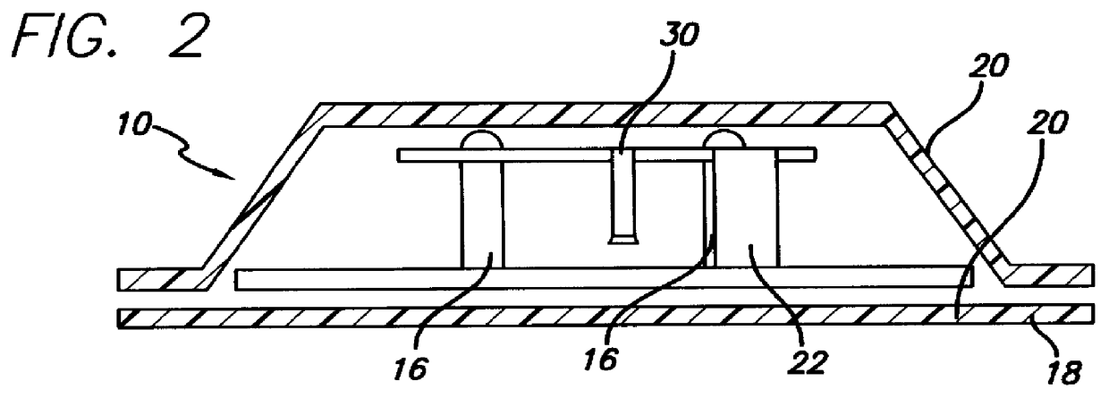
The present invention provides an improved, low profile antenna having better operating characteristics than similar antennae previously known in the art. An example of such prior antennae is shown in FIGS. 1 and 2. Such antennae 10 have a top metal radiator 12 supported above a metal base 14 by standoff insulators 16 made of dielectric or so...


PUM


Abstract

A low-profile antenna has increased broad-banding capacities as well as a lower radiation angle for enhanced cellular or mobile telephone wireless transmissions. Enhancing a basic PIFA antenna, a top metal radiator is notched so as to provide additional corners and greater perimeter length thereby enhancing the bandwidth capabilities of the antenna. Both ground and tuning tabs serve to enhance operational characteristics and a dielectric cover incorporating prismatic qualities serves to lower the radiation angle of transmission from approximately forty degrees (40 DEG ) to twenty degrees (20 DEG ). The prisms provide an operating radiation angle in the range of approximately seventy degrees (70 DEG ) to twenty degrees (20 DEG ). In one embodiment, a sheet of plastic foam slightly thicker than the depth of an associated connector is secured to the underside of the bottom plate to act as a friction seal when the antenna is screwed onto a mating connector, allowing for slight variations in the curvature of the mounting surface. By making the bottom conductive plate only slightly larger than the top radiator, the antenna's resonant frequency becomes independent of ground plane mounting and may not require such a ground plane. Under such circumstances, some adjustment of the tuning parameters may be required in order to provide optimum response.

Description

1. Field of the InventionThis invention relates to antennae for wireless signal transmission, and more particularly to a low profile cellular antenna design meant for facilitating cellular telephone communications in an inconspicuous manner.2. Description of the Related ArtGenerally, disk or patch antennae have a circular disk or rectangular patch configuration and are elevated above a larger ground plane. The transmission line is connected to the center for the circular disk and at an edge or corner for the rectangular patch to serve as the signal feed. Dielectric material is used to support the elevated portion of the antenna above the ground plane.These antennae are often, but not always, made using printed circuit board materials and techniques. When used in mobile radio applications, the bottom ground plane disk is made the same size as the upper disk and must be mounted against the metal body of the vehicle. Such disk antennae can be made with major dimensions on the order of ...

Claims


Application Information

Patent Timeline
IPC IPC(8): H01Q9/04H01Q1/48H01Q1/00H01Q1/42H01Q1/38
CPCH01Q1/38H01Q1/42H01Q9/0442H01Q9/0421H01Q1/48
Inventor OPENLANDER, WAYNE R.
Owner LAIRD CONNECTIVITY INC
Why Eureka
Try Eureka