Image processing apparatus and image processing method

a technology of image processing and image processing, applied in the field of image processing apparatus and image processing method, can solve the problems of inability to obtain encoded data for bits of integer bytes, complicated process, and excessively large quantization value of small difference valu

Inactive Publication Date: 2000-12-05
KK TOSHIBA
View PDF9 Cites 30 Cited by
  • Summary
  • Abstract
  • Description
  • Claims
  • Application Information

AI Technical Summary

Benefits of technology

Another object of the present invention is to provide an image processing apparatus for preventing a wasteful area from taking place in a memory to which compressed image data is written and for easily accessing the memory and an image processing method thereof.
To accomplish such objects, the image processing apparatus according to the present invention switches a quantizing coefficient for quantizing a difference value to an optimum quantizing coefficient corresponding to a feature of each pixel block composed of a predetermined number of pixels of input pixel data. For example, the maximum absolute value of difference values of adjacent pixels of each pixel block of image data is obtained as a feature of the image data. An optimum quantizing coefficient is selected for the maximum absolute value of the difference values and quantized. In reality, when the difference values of adjacent pixels of each pixel block of the image data concentrate in the vicinity of 0, the difference values are quantized with a small quantizing coefficient. Thus, the difference values can be quantized with an optimum quantizing coefficient for each pixel block. Consequently, quantizing errors can be reduced.

Problems solved by technology

However, in this technology, encoded data for bits of integer bytes cannot be obtained.
Thus, a complicated process is required.
Thus, a small difference value is quantized with an excessively large value.
Thus, the quantizing errors increase.

Method used


Image

  • Image processing apparatus and image processing method
  • Image processing apparatus and image processing method
  • Image processing apparatus and image processing method

Examples


Embodiment Construction

Next, an embodiment of the present invention will be described with reference to the accompanying drawings.

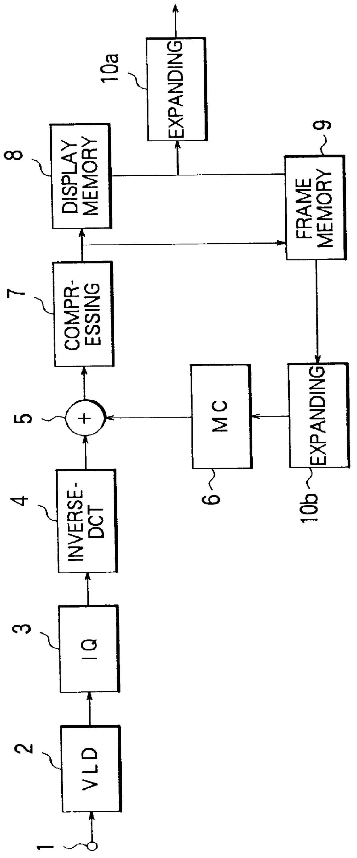
FIG. 1 is a block diagram showing the structure of an image decoding apparatus as an image processing apparatus according to an embodiment of the present invention.

MPEG compressed data is received from an inputting portion. The MPEG compressed data is stored in a receiving buffer (not shown). The receiving buffer compensates the difference of encoding efficiencies of I, P, and B pictures (namely, the difference of the data amounts thereof). A VLD (Variable Length Decoding) portion 2 successively performs a variable-length decoding process for data stored in the receiving buffer. The resultant variable-length decoded data is supplied to an inverse-quantizing portion (IQ) 3. The inverse-quantizing portion (IQ) 3 inversely quantizes the variable-length decoded data and supplies the inversely quantized data to a inverse-DCT portion 4. The inverse-DCT portion 4 inversely orthogonall...


PUM


Abstract

In the image decoding apparatus, the maximum absolute value of difference values of adjacent pixel data of each pixel block of image data is obtained as a feature of the image data. An optimum quantizing coefficient is selected for the maximum absolute value of the difference value. With the selected quantizing coefficient, the maximum absolute value is quantized. When the difference values of adjacent pixel data of each pixel block of image data concentrate in the vicinity of "0", they are quantized with a smaller quantizing coefficient. Thus, with an optimum quantizing coefficient, each pixel block of image data can be quantized. Consequently, quantizing errors can be reduced.

Description

1. Field of the InventionThe present invention relates to an image processing apparatus applicable for an apparatus that decodes image data that has been compressed and encoded corresponding to the MPEG format and to an image processing method thereof.2. Description of the Related ArtAn MPEG decoding apparatus requires a memory with a large storage capacity (for example, a frame memory that stores two frames) for decoding B picture. In recent years, as technologies for reducing the storage capacity of the frame memory, a method for writing a compressed decoded image to a frame memory of an MPEG decoding apparatus has been proposed as in "A study on reduced memory approach in MPEG2 decoder systems", ITE '96 1996 ITE Annual Convention, 23-4 and in "A study on frame memory reduction in MPEG2 decoder systems", THE INSTITUTE OF ELECTRONICS, INFORMATION AND COMMUNICATION ENGINEERS PROCEEDINGS OF THE 1996 IEICE GENERAL CONFERENCE, D-320.In "A study on reduced memory approach in MPEG2 decod...

Claims


Application Information

Patent Timeline
Patent Type & Authority Patents(United States)
IPC IPC(8): G06T9/00H04N1/41H04N19/50H04N19/126H04N19/137H04N19/169H04N19/196H04N19/423H04N19/426H04N19/46H04N19/503H04N19/51H04N19/593H04N19/61H04N19/625H04N19/70H04N19/85H04N19/91H04N19/93
CPCG06T9/007
Inventor ABE, SHUJIFUKUSHIMA, MICHIHIRO
Owner KK TOSHIBA
Why Eureka
Try Eureka