Electric power steering control system

Inactive Publication Date: 2000-12-12
MITSUBISHI ELECTRIC CORP
View PDF4 Cites 98 Cited by
  • Summary
  • Abstract
  • Description
  • Claims
  • Application Information

AI Technical Summary

Benefits of technology

FIG. 16 is a block diagram of an electric po

Problems solved by technology

However, when the torque proportional gain is increased, oscillation of a control system occurs and the driver feels uncomfortable torque oscillation.
Therefore, the torque proportional gain cannot be simply increased.
However, in the prior art, when compensation is made to increase the damping current, this damping compensation functions as resistance when

Method used


Image

  • Electric power steering control system
  • Electric power steering control system
  • Electric power steering control system

Examples


embodiment 1

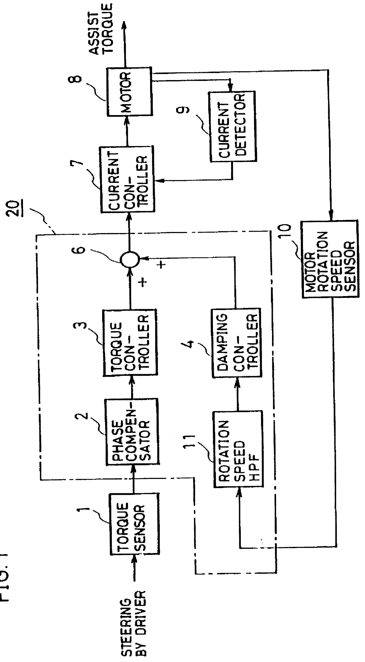
In Embodiment 1, the rotation speed of the motor is detected by the motor rotation speed sensor 10 such as a tachometer generator. A motor rotation angle signal may be detected by a rotary encoder, for example, and differentiated to obtain the rotation speed of the motor.

In Embodiment 1, the target current is obtained from the output of the torque controller 3 and the output of the damping controller 4. Like the prior art, a compensation controller 5 which comprises a friction compensation controller 5a and an inertia compensation controller 5b may be added to obtain the target current by further adding the output of the friction compensation controller and the output of the inertia compensation controller.

Thus, in this Embodiment 1, after a steering frequency component is removed from the motor rotation speed signal detected by the motor rotation speed sensor 10 using the rotation speed HPF 11, the damping current is computed by the damping controller 4 based on the output of the r...

embodiment 2

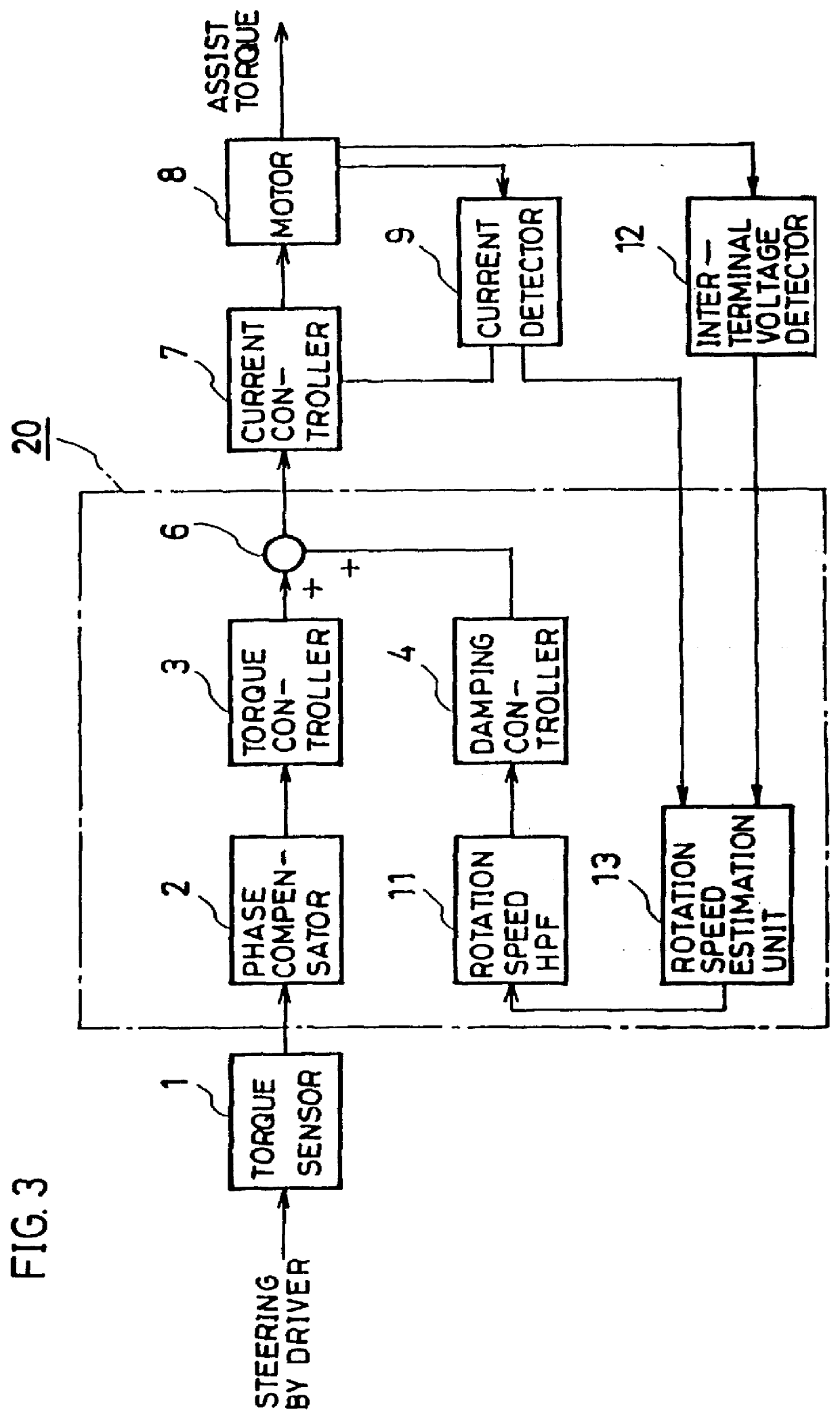
FIG. 3 is a block diagram showing an electric power steering control system according to Embodiment 2 of the present invention. In the above Embodiment 1, the rotation speed HPF 11 is provided and a damping current is computed based on the output of the rotation speed HPF which is obtained by removing a steering frequency component from the motor rotation speed signal from the motor rotation speed sensor 10. In Embodiment 2, as shown in FIG. 3, the motor rotation speed sensor 10 is omitted, an inter-terminal voltage detector 12 for detecting voltage between the terminals of the motor 8 and a rotation speed estimation unit 13 for estimating the rotation speed of the motor 8 based on an inter-terminal voltage detection value detected by the inter-terminal voltage detector 12 and a drive current detection value detected by the current detector 9 are provided to estimate the rotation speed of the motor, a motor rotation speed estimation signal output from the rotation speed estimation u...

embodiment 3

FIG. 5 is a block diagram showing an electric power steering control system according to Embodiment 3 of the present invention. In Embodiment 2, the motor rotation speed estimation signal .omega.est.sub.-- bk is obtained by estimating the rotation speed of the motor by the rotation speed estimation unit 13 for estimating the rotation speed of the motor from the inter-terminal voltage detection value Vt.sub.-- sns of the motor and the drive current detection value Isns. In this Embodiment 3, as shown in FIG. 5, a rotation speed estimation unit 13 for estimating the rotation speed of the motor 8 based on the target current and the inter-terminal voltage instruction value from the current controller 7 is provided to compute the motor rotation speed estimation signal .omega.est.sub.-- bk, and this motor rotation speed estimation signal .omega.est.sub.-- bk is applied to the above rotation speed HPF 11 to compute a damping current based on the output of the rotation speed HPF from which ...


PUM


Abstract

An electric power steering control system reducing steering torque without making a driver feel uncomfortable torque oscillation, including a rotation speed observer for estimating the rotation speed of a motor based on the output of a torque sensor high pass filter (HPF) and the output of a drive current HPF obtained by removing a steering frequency component from a drive current detection value.

Description

1. Field of the InventionThe present invention relates to an electric power steering control system for assisting steering force with a motor.2. Description of the Prior ArtFIG. 16 is a block diagram showing the constitution of an electric power steering control system of the prior art disclosed in Mitsubishi Technical Report Vol. 70, No. 9, pp.43-48, for example. In FIG. 16, reference numeral 1 denotes a torque sensor for detecting steering torque when a driver steers an automobile; 2, a phase compensator for improving the frequency characteristics of the output signal of the torque sensor 1; 3, a torque controller for computing an assist torque current for assisting the steering torque based on the phase compensated output of the torque sensor 1; 4, a damping controller for computing a damping current based on the rotation angle speed .omega.M of a motor 8 computed by unshown motor angle speed computing means, for example, 5 a compensation controller which consists of a friction c...

Claims


Application Information

Patent Timeline
IPC IPC(8): B62D5/04B62D6/00B62D101/00B62D119/00B62D137/00
CPCB62D5/0472B62D5/0463
Inventor KURISHIGE, MASAHIKOINOUE, NORIYUKIKIFUKU, TAKAYUKIZENIYA, SUSUMU
Owner MITSUBISHI ELECTRIC CORP
Why Eureka
Try Eureka