Spool having a surface treatment for use in a fishing reel

a technology for fishing reels and spools, which is applied in the field of spools for use in fishing reels, can solve the problems of reducing the carrying distance of fishing lines, affecting the smoothness of the surface of the spool, and affecting the appearance of the surface, so as to achieve the effect of enhancing the surface smoothness and glossy appearance, reducing the weight of the spool, and simple surface treatmen

a technology for fishing reels and spools, which is applied in the field of spools for use in fishing reels, can solve the problems of reducing the carrying distance of fishing lines, affecting the smoothness of the surface of the spool, and affecting the appearance of the surface, so as to achieve the effect of enhancing the surface smoothness and glossy appearance, reducing the weight of the spool, and simple surface treatmen

US6164577AInactive Publication Date: 2000-12-26DAIWA SEIKO CORPORATION

Image

  • Spool having a surface treatment for use in a fishing reel
  • Spool having a surface treatment for use in a fishing reel
  • Spool having a surface treatment for use in a fishing reel

Examples


Embodiment Construction

Now, description will be given below of a spool for use in a fishing reel according to an embodiment of the invention with reference to the accompanying drawings.

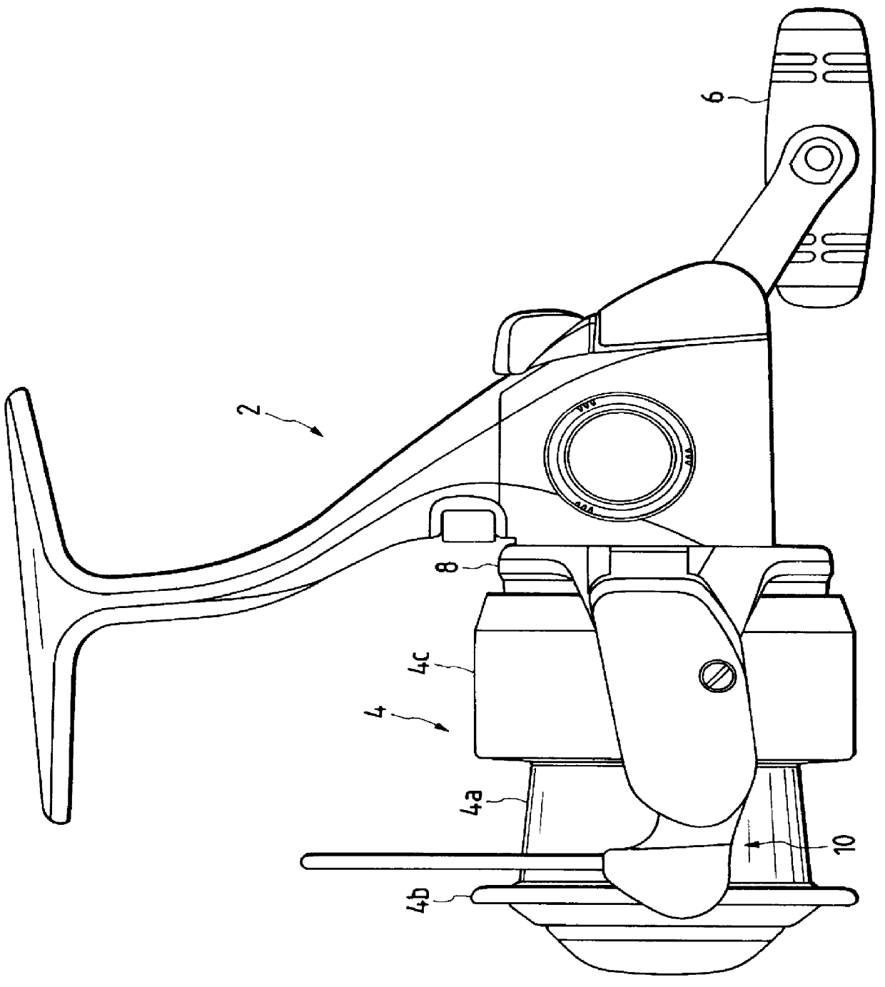
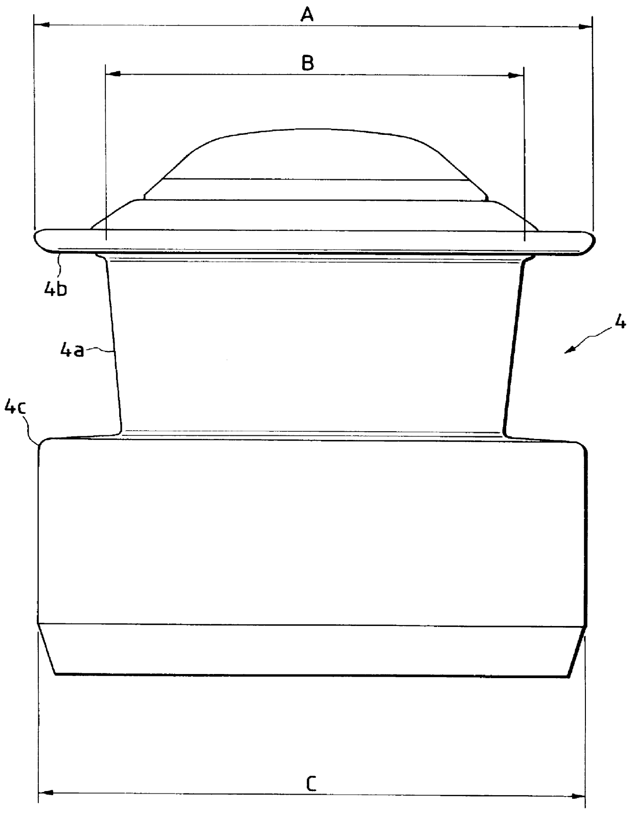
In FIG. 1, there is shown the structure of a spinning reel 2 for fishing, as an example to which the present embodiment is applied; and, in FIG. 2, there is shown the structure of a spool 4 which is applied to the spinning reel 2 for fishing.

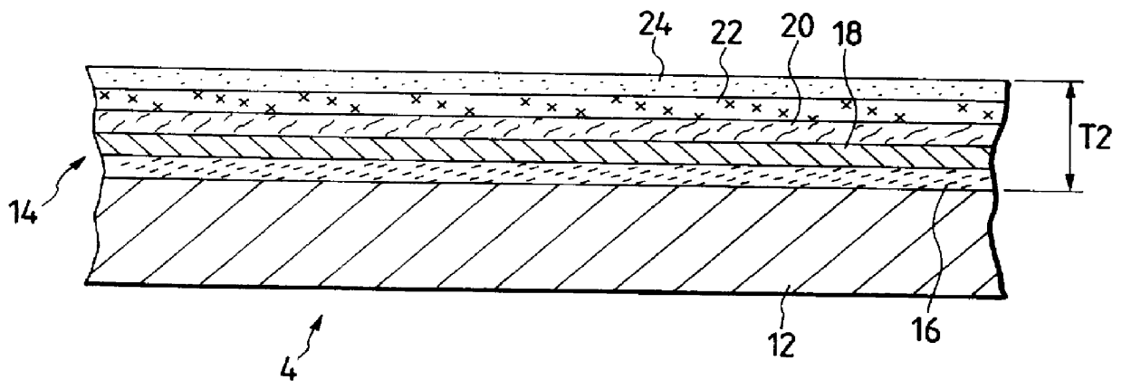
Referring now to the structure of the spool 4, such surface treatment (see FIG. 3) as will be discussed later is enforced on the whole of the surface of the spool 4; and, the spool 4 comprises a fishing line winding barrel portion 4a, and a front flange portion 4b and a rear flange portion 4c which are formed on opposite sides of the fishing line winding barrel portion 4a.

Also, the fishing line winding barrel portion 4a is tapered at a given angle in such a manner that the diameter thereof decreases continuously and smoothly as it goes from the front side thereof toward the rear side th...


PUM


Abstract

A spool for use in a fishing reel, which is structured such that, by combining an electrolytic plating method, a non-electrolytic plating method, and a dry coating method properly and selectively, a metal film layer (14) having one of desired film thicknesses (T1, T2 and T3) is formed on the surface (outer peripheral surface) of the spool base material (12).

Description

1. Field of the InventionThe present invention relates to a spool for use in a fishing reel and, in particular, to such spool the surface of which is treated in such a manner that not only the weight of the spool can be reduced but also the gloss of the outside of the spool and the durability thereof can be enhanced.2. Description of the Related Prior ArtIn a fishing reel, so as to enhance its operation efficiency, portability, and the like, conventionally, reduction of the weight has been proceeded. For this purpose, in such fishing reel, in most cases, there is used a spool in which, for example, instead of metal material such as aluminum or the like, resin material is used as the base material of the spool.Especially, in a spool which is composed of a fishing line winding barrel portion and front and rear flange portions, in an actual fishing operation, when a fishing line with a load applied thereto is uniformly wound around the fishing line winding barrel portion of the spool, ...

Claims


Application Information

Patent Timeline
26 Dec 2000
Publication
US6164577A
IPC
A01K89/00; A01K89/01
CPC
A01K89/0111; A01K89/015; A01K89/01931
Inventors
KOIKE, MAMORU