
Tapered shank rivet

Inactive Publication Date: 2001-01-09
TEXTRON IPMP +1
View PDF17 Cites 30 Cited by
  • Summary
  • Abstract
  • Description
  • Claims
  • Application Information

AI Technical Summary

Benefits of technology

It is an additional object of the present invention to provide a method and device for blind riveting which improves hole-fill.
It is a related object of the present invention to provide a method and device for blind riveting which improves hole-fill at the head / shank juncture.
It is a further object of the present invention to provide a method and device for blind riveting which increases the strength of the structural joint created.
It is a related object of the present invention to provide a method and device for blind riveting which increases the life of the structural joint and delays the onset of fatigue failure.
Yet another object of the present invention is to provide a method and apparatus for blind riveting which reduces the force or end load necessary to fully drive and seat a rivet in a hole.
Accordingly, the present invention provides a method of blind riveting and a blind rivet which improve hole-fill in the region of the head / shank juncture and increase the strength of the rivet joint. The present invention also provides a method of blind riveting and a blind rivet which reduce the force necessary to seat and fully drive the rivet in the hole. A blind rivet according to the invention includes an interference fit shank portion between the head and the generally axially aligned or straight portion of the sleeve. The interference fit shank portion may be tapered or may include a tapered transition between the sleeve and a generally straight interference fit shank portion.

Problems solved by technology

Such solid rivets are generally upset at one end; that is, a load is applied to both ends of the rivet to deform the material of the rivet tail to form a structural joint.
The prior art method of blind riveting suffers from a number of problems.
A problem which may arise is insufficient engagement between the rivet and the work piece at the juncture of the rivet head and sleeve or shank.
Insufficient engagement, commonly termed "poor under-head hole-fill" reduces the strength of the rivet joint and can lead to premature failure of the work piece.
Another problem is that prior art methods may require a considerable force or end load to drive the rivet securely into the work piece.
The need to use considerable force may have a number of undesirable consequences.
These include reduced life of the riveting apparatus, strain on the operator, and possible damage to the work piece.
A further problem with conventional methods is that they are often inadequate to draw the sheets of material entirely together.
The gaps interfere with the formation of a tight and secure joint.
Such gaps are particularly detrimental in the aerospace industry where fuel and gas tight joints are essential.
Moreover, moisture may gather in the gaps, which can lead to corrosion and failure.

Method used


Image

  • Tapered shank rivet
  • Tapered shank rivet
  • Tapered shank rivet

Examples


Embodiment Construction

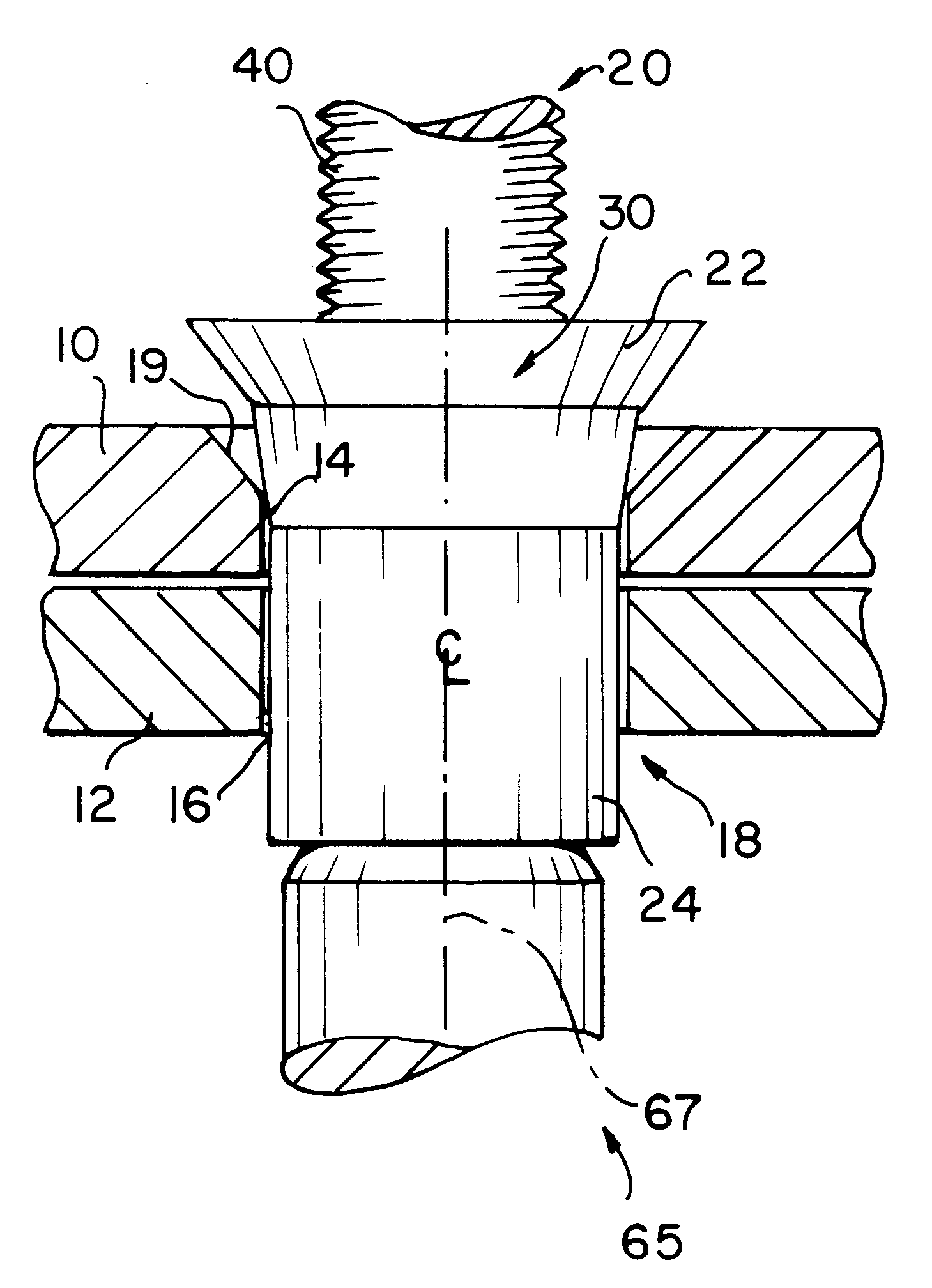
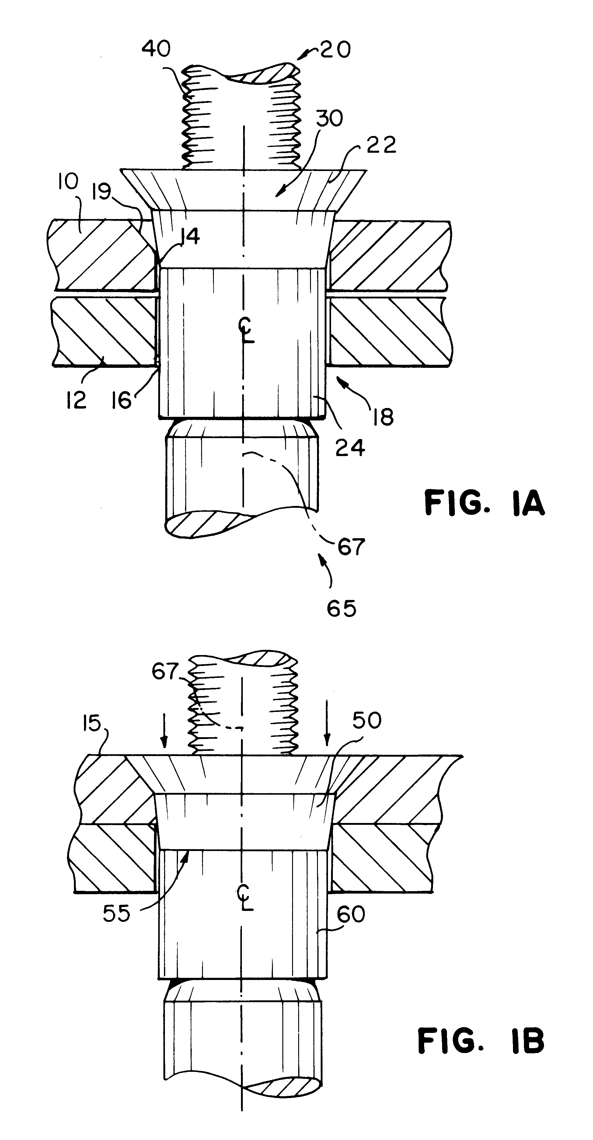
Reference is now invited to FIGS. 1A and 1B which show a blind rivet assembly according to the invention. Specifically, FIGS. 1A and 1B illustrate the riveting together of a work piece, comprising a pair of panels, sheets, or work pieces 10 and 12, using a blind rivet 20 according to the invention. The work pieces 10, 12 include aligned holes or apertures 14, 16 which form a bore 18 for receiving the blind rivet 20 of the present invention. The holes 14, 16 may be drilled or otherwise suitably formed in the work pieces 10, 12. The bore 18 is preferably substantially straight and cylindrical. A tapered or countersink region 19, however, may be provided in an upper portion of the bore 18 for accommodating a flush type rivet head. Such a tapered or countersink region 19 is shown in FIG. 1A. It will be apparent to those skilled in the art, however, that a radially extending head or protruding head may also be used in the present invention and in that case, the entire bore 18 would be su...


PUM

PropertyMeasurementUnit
Angleaaaaaaaaaa
Forceaaaaaaaaaa
Corrosion propertiesaaaaaaaaaa

Abstract

An improved method of blind riveting and an improved blind rivet have been described. The blind rivet of the present invention includes an interference fit shank portion which ensures adequate hole-fill and produces work hardening in a work piece. The blind rivet of the present invention also produces a drawing effect, reducing the force necessary to securely seat the rivet in a hole.

Description

This invention relates to rivets and in particular to a blind rivet having structures which produce improved results.The use of rivets to fasten together two sheets of material is well-known. The sheets of material are provided with apertures or holes which are formed in the sheets when positioned for fastening. The sheets are arranged in overlapping relation so that the apertures are aligned and a rivet is inserted into the aligned holes. The rivet, which generally includes a head and a body portion, is then upset to provide a structural joint between the two sheets of material.The manner of upsetting the rivet depends on the type of rivet used and in particular on whether the rivet is a solid or blind rivet. Solid rivets are often used in fastening operations where the opposite ends of work pieces which are joined are both accessible. In other words, both the work end and the free end of the rivets are accessible during the fastening operation. Such solid rivets are generally upse...

Claims


Application Information

Patent Timeline
IPC IPC(8): F16B19/04F16B19/10B21J15/00F16B35/04
CPCF16B19/1054
Inventor PRATT, JOHN D.ESHRAGHI, SOHEIL
Owner TEXTRON IPMP
Features
  • Generate Ideas
  • Intellectual Property
  • Life Sciences
  • Materials
  • Tech Scout
  • Unparalleled Data Quality
  • Higher Quality Content
  • 60% Fewer Hallucinations
Learn More