Method of and apparatus for controlling the operation of a clutch in the power train of a motor vehicle

a technology of motor vehicles and clutches, which is applied in the direction of mechanical equipment, belts/chains/gearings, and control of gears, etc., can solve the problems of preventing the engine from developing an adequate power and the engine from reaching an rpm, and achieve the effect of reliable and economical

Inactive Publication Date: 2001-01-09
LUK GETRIEBE SYST
View PDF13 Cites 39 Cited by
  • Summary
  • Abstract
  • Description
  • Claims
  • Application Information

AI Technical Summary

Benefits of technology

An object of the invention is to provide a reliable and economical method of operating a torque transmitting system (such as a friction clutch, another clutch or a hydrokinetic torque converter with a bypass clutch) in the power train of a motor vehicle.
Under certain circumstances, the improved method can comprise the steps of monitoring the RPM of the output element of the prime mover, reducing the rate of torque transmission by the torque transmitting system when the monitored RPM of the output element is below the desired RPM, increasing the rate of torque transmission by the torque transmitting system when the monitored RPM of the output element exceeds the desired RPM, respectively generating first and second signals which denote the monitored RPM and the desired RPM of the output element of the prime mover, and processing the first and second signals. The steps of reducing and increasing the rate of torque transmission by the torque transmitting system then include adjusting the torque transmitting system as a function of the processed first and second signals.

Problems solved by technology

However, when the circumstances of use of a motor vehicle depart from normal circumstances, for example, when the vehicle is utilized on mountain roads or elsewhere well above the sea level (turbo engines are particularly sensitive under such circumstances of use), when the outside temperature is very low, and / or under certain other circumstances, it can happen (especially while setting the vehicle in motion) that the disengagement of the clutch is excessive which prevents the engine from reaching an RPM at which it can or could furnish a maximum torque.
This can prevent the engine from developing an adequate power during starting of the motor vehicle.

Method used


Image

  • Method of and apparatus for controlling the operation of a clutch in the power train of a motor vehicle
  • Method of and apparatus for controlling the operation of a clutch in the power train of a motor vehicle
  • Method of and apparatus for controlling the operation of a clutch in the power train of a motor vehicle

Examples


Embodiment Construction

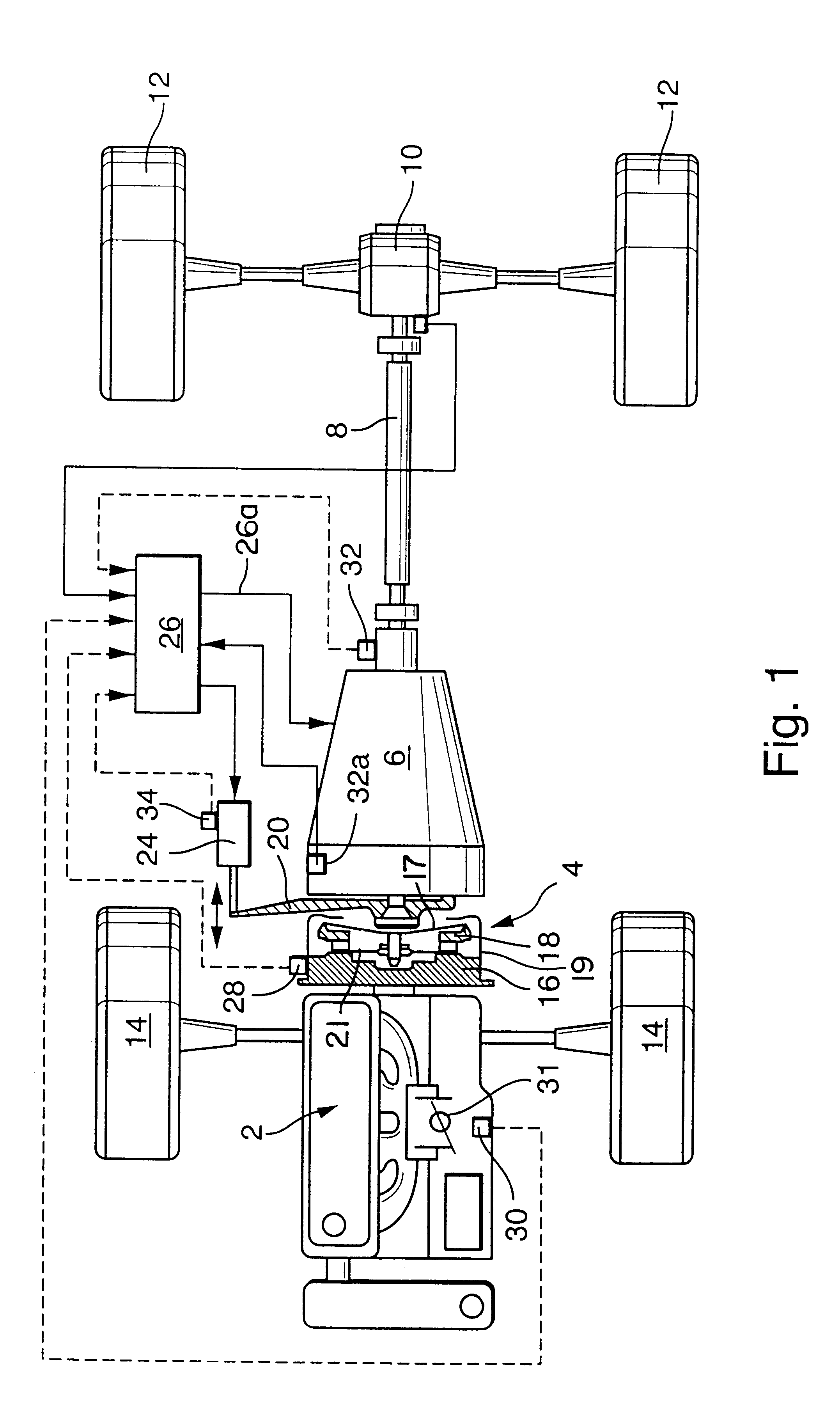
FIG. 1 shows a portion of a motor vehicle having a power train including a prime mover 2 (such as an internal combustion (Otto) engine) with a rotary output element (such as a camshaft or a crankshaft) which drives a flywheel 16 constituting the counterpressure plate of an automated torque transmitting system 4 in the form of a friction clutch further having an axially movable pressure plate 18 biased by a clutch spring 17 which reacts against a clutch housing 19. When the clutch 4 is at least partially engaged, the clutch spring 17 reacts against the housing 19 and causes the pressure plate 18 to urge the friction linings of a rotary clutch disc or clutch plate 21 against the adjacent friction surface of the flywheel 16 so that the clutch disc 21 can rotate the input element (e.g., a shaft) of an automated transmission 6. The output shaft 8 of the transmission 6 drives a differential 10 for the axles of the rear wheels 12 of the motor vehicle. The front wheels 14 of the illustrated...


PUM


Abstract

The extent of engagement of an automatically adjustable friction clutch in the power train of a motor vehicle, wherein the clutch receives torque from a rotary output element of an engine and transmits torque to the rotary input element of a transmission, is determined by an electronic control unit in conjunction with an actuator which is responsive to signals from the control unit. Under normal circumstances, the adjustment of the clutch is selected on the basis of control signals which depend upon the actual RPM of the output element and the RPM of the input element. When the actual RPM of the output element departs from a desired RPM, the control signal is altered to reduce the rate of torque transmission by the clutch upon a determination that the actual RPM is below the desired RPM, and to increase the rate of torque transmission by the clutch when the actual RPM exceeds the desired RPM.

Description

The invention relates to power trains of motor vehicles in general, and more particularly to improvements in methods of and in apparatus for operating adjustable torque transmitting systems (e.g., in the form of engageable and disengageable friction clutches) of such power trains.As a rule, or at least in many instances, the operation of the friction clutch in the power train of a motor vehicle (normally but not necessarily between the rotary output element of a prime mover and the rotary input element of a change-speed transmission) is regulated automatically by one or more actuators (e.g., electric motors in conjunction with gearings and / or fluid-operated cylinder and piston units) which receives or receive signals from a computerized control unit. The control unit normally processes signals denoting various operational parameters of the motor vehicle and / or of its power train; and its output signal to the actuator or actuators reflects the intensity or intensities (and / or other c...

Claims


Application Information

Patent Timeline
Patent Type & Authority Patents(United States)
IPC IPC(8): B60K23/02B60K17/00B60K17/02B60K23/00F16D48/00F16D48/06F16D48/02B60W10/02B60W10/06B60W30/18F16D48/08F16H63/46
CPCB60K17/02B60W10/02B60W10/06B60W10/107B60W30/18F16D48/06F16H63/46B60K23/02Y10T477/70B60K2741/025B60W2510/0638B60W2510/1015B60W2710/027B60W2710/0644B60W2710/0661Y10T477/6424Y10T477/753Y10T477/6418Y10T477/75Y10T477/6425Y10T477/6422F16D48/066F16D2500/10412F16D2500/1088F16D2500/3026F16D2500/30401F16D2500/3067F16D2500/30816F16D2500/30825F16D2500/70605F16D2500/70615B60W10/04B60W30/1819B60W2050/001B60W30/18027
Inventor REUSCHEL, MICHAEL
Owner LUK GETRIEBE SYST
Why Eureka
Try Eureka