Cavitation enhanced liquid atomization

a liquid atomization and cavitation technology, applied in the direction of catalytic naphtha reforming, thermal non-catalytic cracking, chemical/physical/physicochemical processes, etc., can solve the problem of fluid cat cracking as it is also called, viscous fluids at high flow rates, and enhanced corrosion

Inactive Publication Date: 2001-01-09
EXXON RES & ENG CO
View PDF4 Cites 9 Cited by
  • Summary
  • Abstract
  • Description
  • Claims
  • Application Information

AI Technical Summary

Problems solved by technology

Atomizing relatively viscous fluids at high flow rates, such as the heavy petroleum oil feeds used in fluidized catalytic cracking (FCC) processes, or fluid cat cracking as it is also called, is particularly challenging.
However, the use of steam produces sour water, which enhances corrosion.
Sour water is also environmentally unfriendly and must therefore be treated before disposal.
At any given temperature, the greater the pressure differential between the pressure in the atomizing zone and the vapor pressure of the cavitating fluid in the atomizing zone, the more rapid and violent will be its expansion, which translates i

Method used


Image

  • Cavitation enhanced liquid atomization
  • Cavitation enhanced liquid atomization

Examples


example 1

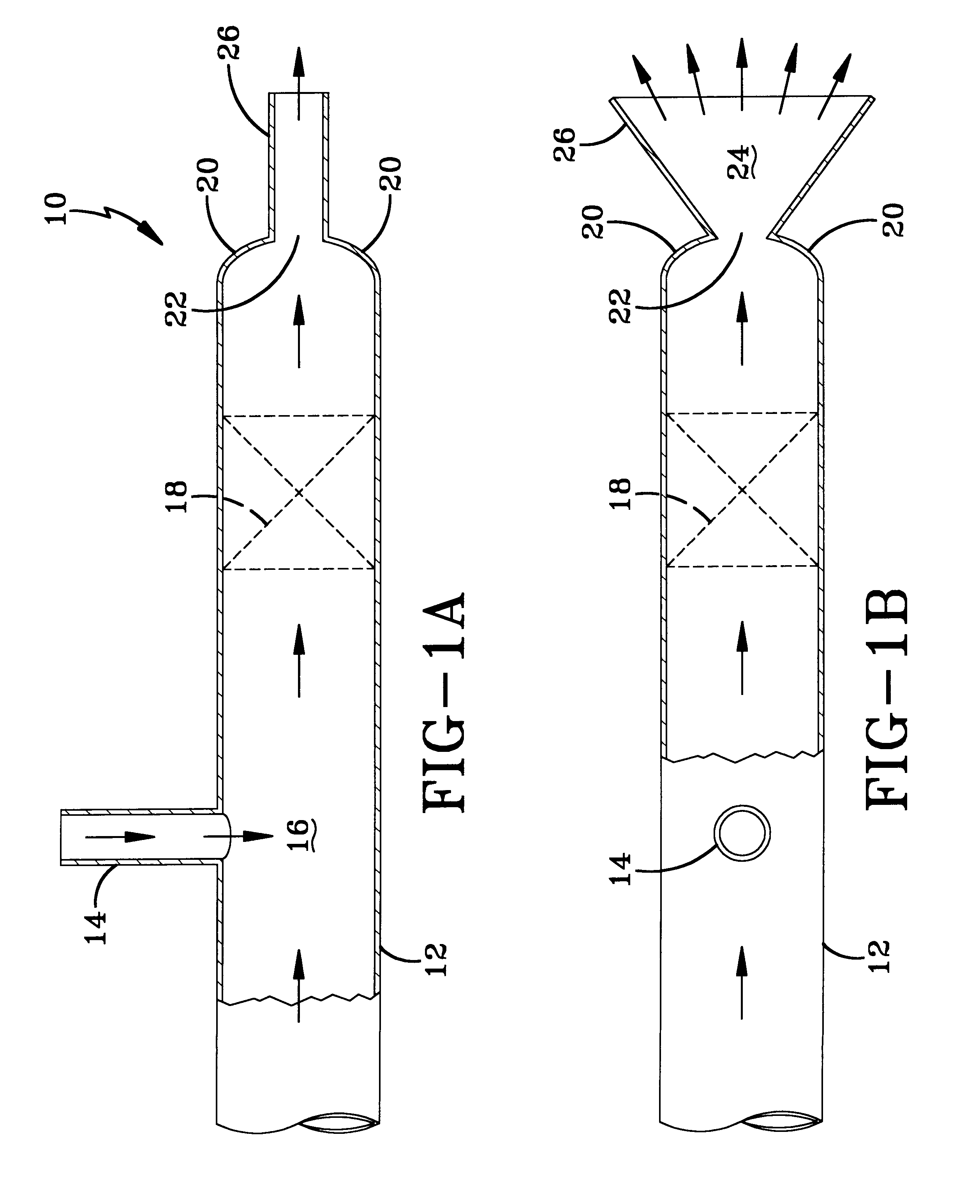
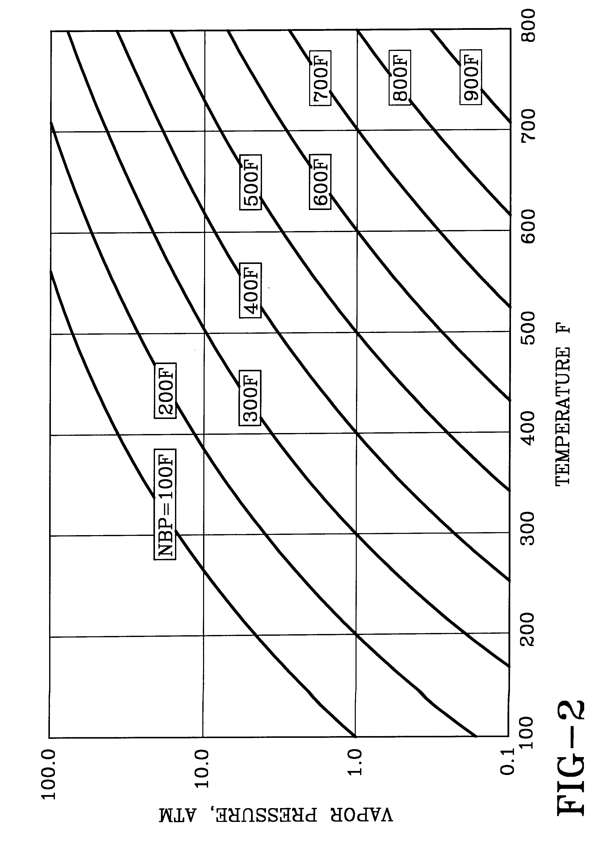
The lower boiling cavitating fluid must be soluble in, and compatible with, the liquid to be atomized and with any upstream processes conditions for each specific application. By way of an illustrative example specifically for the practice of the invention for atomizing the liquid oil feed to an FCC unit, reference is made to a vapor pressure graph for hydrocarbons, shown in FIG. 2. For the purposes of this example, this graph is a simplified version of the one disclosed by Maxwell and Bonnell, in an article titled Derivation and Precision of a New Vapor Pressure Correlation for Petroleum Hydrocarbons, which appeared in Industrial and Engineering Chemistry, v.49, pages 1187-1196 (1957). The pressure in the fluid conduit upstream of the atomizing orifice is assumed to be 7 atmospheres and the pressure on the downstream side of the orifice, in the atomization zone, is assumed to be 3 atmospheres. For an upstream temperature of 750-800.degree. F., the cavitating liquid must be a liquid...

example 2

Simple comparative experiments using an aqueous acetone solution were conducted to demonstrate cavitation-enhanced atomization. Sharp angle orifice plates were used for the atomizing means, which in these experiments were bores in the plates and their length to diameter (L / D) ratios were 1.4:1 and 7:1. Both were cylindrical bores having an inner diameter of 350 .mu.m, with the plate thickness determining the L / D ratio. The main components of the experimental setup were a pressure vessel, a heated liquid hose, a monosize drop generator, and a heated air chamber purged with flowing nitrogen at atmospheric pressure. The atomizing pressure was measured in the pressure vessel. Images of the break-up of the fluid exiting each orifice and spray patterns were taken with a Greenfield Speedview 700 imaging system. Droplet images of the sprays were taken with a CCD camera. In every case, the orifice opened into the heated air chamber at the downstream side. The temperature in the chamber was i...


PUM


Abstract

A cavitation enhanced atomizing process comprises forming a flowing solution of the liquid to be atomized and a lower boiling cavitating liquid. This flowing solution is then contacted with a pressure reducing means, at a temperature below the bubble point of the cavitating liquid in the solution, to produce cavitation bubbles. These bubbles comprise cavitation liquid vapor and the bubble nucleation produces a two-phase fluid of the bubbles and liquid solution. The two-phase fluid is passed downstream into and through an atomizing means, such as an orifice, and into a lower pressure atomizing zone, in which the bubbles vaporize to form a spray of liquid droplets. The nucleated bubbles also grow in size as the so-formed two-phase fluid passes downstream to and through the atomizing means.

Description

BACKGROUND OF THE DISCLOSURE1. Field of the InventionThe invention relates to cavitation enhanced liquid atomization. More particularly, the invention relates to atomizing a fluid comprising a solution of the liquid to be atomized and a lower boiling cavitation liquid, by contacting the fluid under pressure and while flowing, with a pressure reducing means to reduce the fluid pressure and thereby produce nucleation and growth of bubbles comprising vapor of the cavitation liquid in the fluid, at a temperature below the bubble point of the solution, and then passing the fluid through an atomizing means into a lower pressure atomizing zone. Bubble nucleation is induced upstream of the atomizing means. This is useful for atomizing a hot FCC feed oil into a catalytic cracking reaction zone, using a lower boiling hydrocarbon as the cavitation liquid.2. Background of the InventionFluid atomization is well known and used in a wide variety of applications and processes. These include, for ex...

Claims


Application Information

Patent Timeline
IPC IPC(8): B01J8/00B01J19/00C10G11/18B01J8/24B05B7/04
CPCB01J8/1827C10G11/18B01J19/008
Inventor DRAEMEL, DEAN C.NAHAS, NICHOLAS C.HO, TEH CHUNG
Owner EXXON RES & ENG CO
Why Eureka
Try Eureka