Electric welding apparatus and method

a welding apparatus and electric welding technology, applied in welding apparatus, other domestic objects, manufacturing tools, etc., can solve the problems of speed limitation, electrodes are not oriented in tandem relationships, arrangement cannot use stt technology or other short-circuit welding, etc., to increase the speed of deposition, increase the speed of molten metal, and increase the effect of spatter

Inactive Publication Date: 2001-01-09
LINCOLN GLOBAL INC
View PDF9 Cites 116 Cited by
  • Summary
  • Abstract
  • Description
  • Claims
  • Application Information

AI Technical Summary

Benefits of technology

In accordance with the invention, two consumable electrodes are positioned on the adjacent sidewalls of the plates near the open root gap so that the travel speed of the pipe welding mechanism is not limited by the physical factors limiting the travel speed in the single electrode system. By using the present invention, the current for each welding arc is adjusted for proper penetration and fusion into the land and root of each pipe section or plate being welded. The side-by-side consumable electrodes are spaced so that each electric arc is impinging on the same common welding puddle. Surface tension forces will assimilate the molten metal from the two side-by-side consumable electrodes to join the molten metal, thus, forming a single weld puddle. Consequently, the metal from two electrodes is introduced into the molten metal puddle from the sides of the gap as opposed to a single electrode melting in the center of the gap as done in the prior single electrode system. Consequently, the puddle accepts substantially increased molten metal and the speed of depositing metal is increased. Since the welding arcs are impinging on a solid metal surface, the resulting jet forces do not blow through into the interior of the pipe, irrespective of the speed that the mechanical bug moves along the gap. Consequently, higher welding currents and faster travel speeds are made possible by the use of the present invention.
Still a further object of the present invention is the provision of an apparatus and method, as defined above, which apparatus and method uses side-by-side electrodes without the disadvantages of forcing one electrode to be driven and melted by a physical or electrical condition of the other electrode.
A further object of the present invention is the provision of an apparatus and method, as defined above, which apparatus and method allows rapid deposition of molten metal in the open root of a pipe welding procedure without the tendency for blowthroughs.

Problems solved by technology

This is a speed limitation, as explained above, experienced even when a higher deposition rate is obtained by the use of two or more tandem electrodes.
However, the electrodes are not oriented in a tandem relationship.
It has been suggested that side-by-side consumable electrodes could be used for pipe welding; however, this arrangement could not use STT technology or other short circuit welding because, in short circuit welding, the arc current must be changed rapidly upon the impending formation of a fuse from an electric pinching of the molten metal.
Side-by-side electrodes were thus impractical when using STT technology.
Since an STT welder controls the heat in a manner allowing superior open root pass welding in pipe welding, side-by-side electrodes were not practical for pipe welding.
Consequently, proper spatter reduction is nearly impossible and the advantage of STT technology is not realized.
Thus, all efforts to use side-by-side consumable electrodes in the formation of the initial open root pass of a pipe welding procedure have been unsuccessful.
This increased spatter.

Method used


Image

  • Electric welding apparatus and method
  • Electric welding apparatus and method
  • Electric welding apparatus and method

Examples


Embodiment Construction

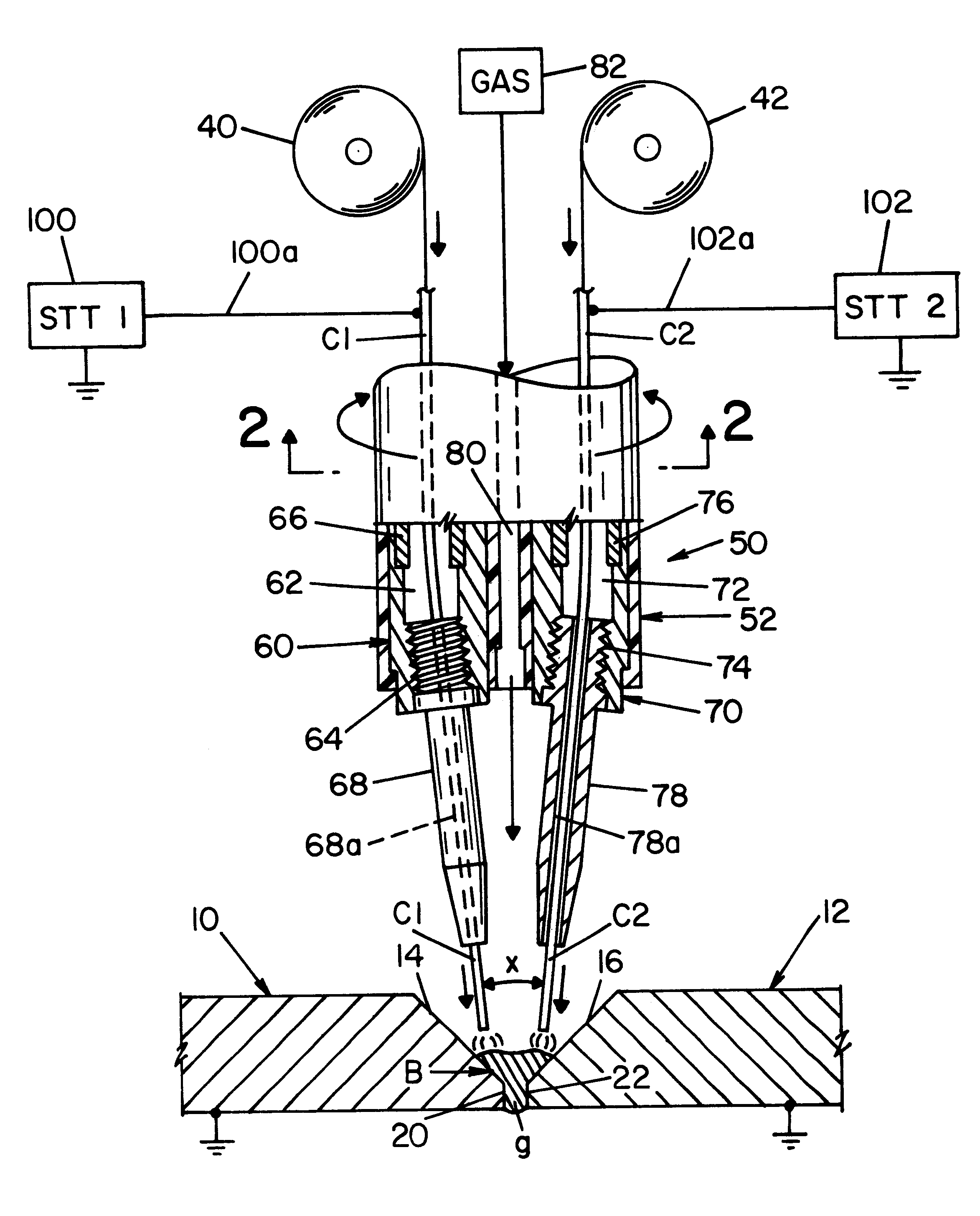
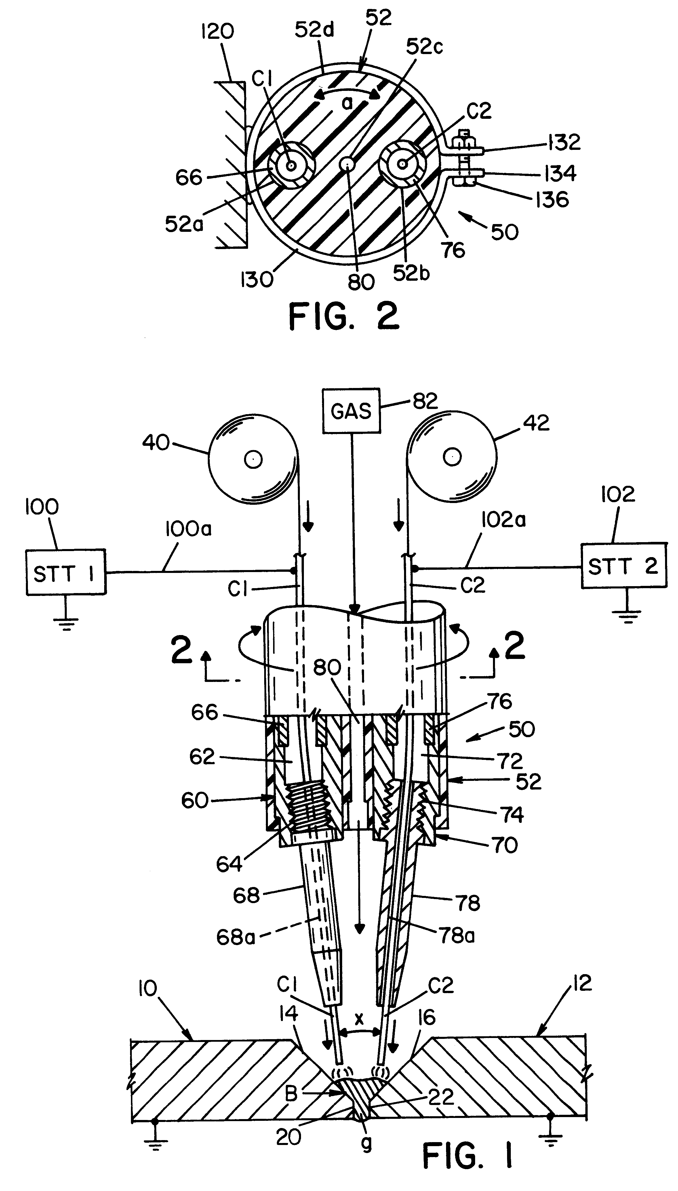
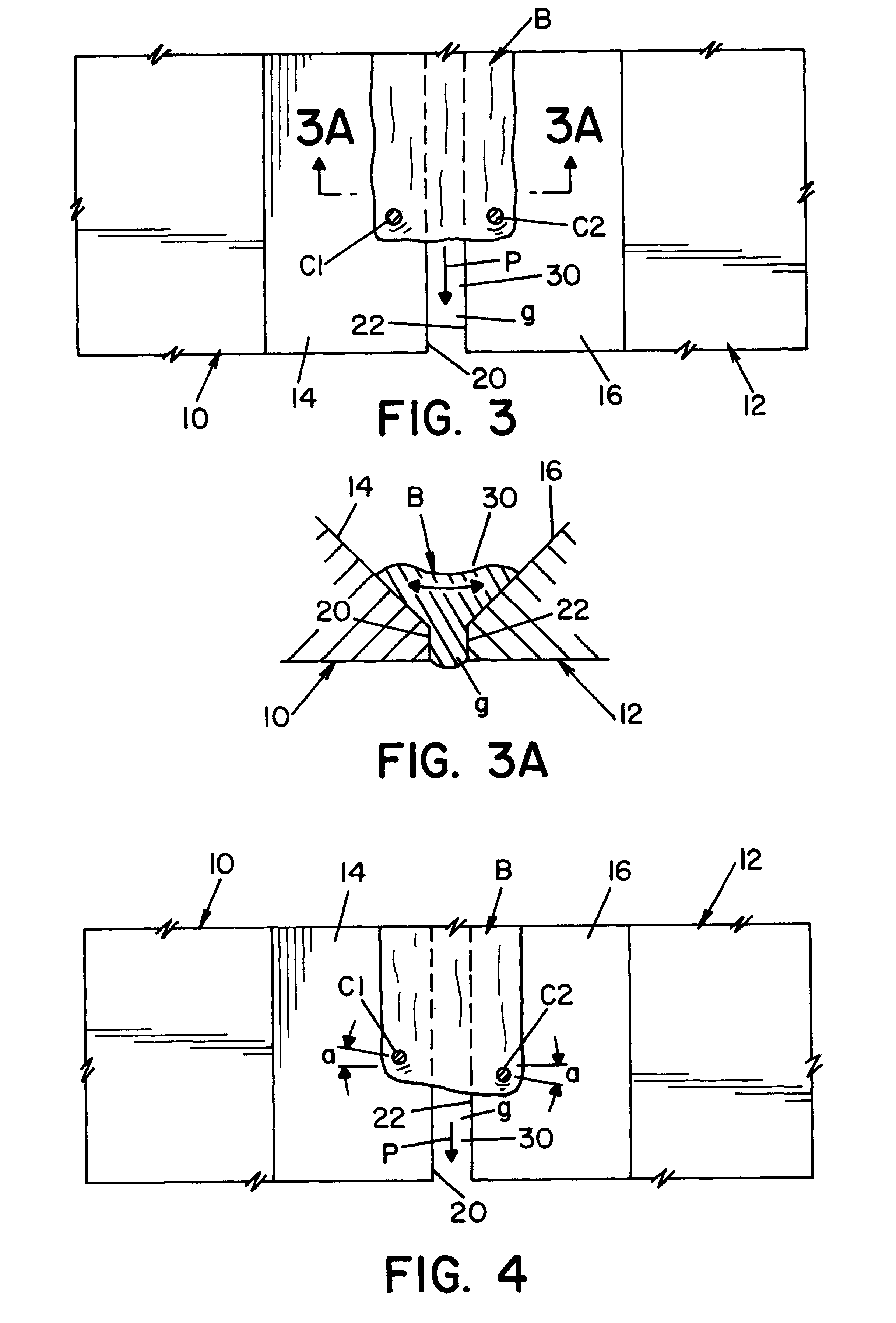
Referring now to FIGS. 1-3, steel plates 10, 12 which, in practice, are the cylindrical ends of two adjacent pipe sections that have been brought together and, then, retracted to produce a small spacing or gap g. Plates 10, 12 are formed from diverging sidewalls 12, 16 and facing edges or ends 20, 22, respectively, to define an open root joint 30. This joint is fairly narrow at gap g and opens outwardly toward the top of plates 10, 12. Open root joint 30 extends in a path P, best shown in FIG. 3, which path in a pipe welding installation is cylindrical about the central axis of the pipe sections. During use of the present invention, a molten metal puddle B is formed by melting consumable electrodes, or welding wires, C1, C2. These wires are melted and by surface tension action form into the molten metal puddle at a controlled temperature allowing the molten metal to extend through gap g between edges or ends 20, 22. Puddle B solidifies to join the pipe sections together in accordanc...


PUM

PropertyMeasurementUnit
diameteraaaaaaaaaa
frequencyaaaaaaaaaa
currentaaaaaaaaaa

Abstract

An apparatus and method for welding the gap between two ends of adjacent first and second pipe sections comprising: moving a first consumable electrode along the end of the first pipe section; moving a second consumable electrode along the end of the second pipe section; moving the electrodes in unison in side by side relationship on opposite sides of the gap; applying a first welding current to the first electrode; and, applying a second welding current to the second electrode, separate from the first welding current and, optionally, a mechanism for adjusting the spacing of the electrodes.

Description

INCORPORATION BY REFERENCEThe present invention involves the use of two side-by-side consumable electrodes for welding the root pass defined by the gap between two spaced ends of pipe sections being welded together in the field. In pipe welding, the consumable electrode is moved toward the space between the pipe sections from a wire feeder while the torch carrying the electrode and introducing electrical current to the electrode moves around the pipe sections. This movement is accomplished by a mechanical arrangement often referred to as a "bug." Such torch moving mechanism used in the present invention is illustrated in Parker U.S. Pat. No. 5,676,857 wherein a single electrode is moved by a welding bug on a track supported adjacent the gap being welded. This patent is incorporated by reference herein showing the environment to which the present invention is directed, so that the bug and guide track used with the present invention need not be repeated. The invention involves the use...

Claims


Application Information

Patent Timeline
Patent Type & Authority Patents(United States)
IPC IPC(8): B23K9/173B23K9/00B23K9/028B23K101/06
CPCB23K9/1735B23K9/00
Inventor STAVA, ELLIOTT K.
Owner LINCOLN GLOBAL INC
Why Eureka
Try Eureka