
Opto-mechanical device

a technology of optical components and mechanical components, applied in the field of optical components, can solve the problems of high manufacturing cost, large difficulty and cost,

Inactive Publication Date: 2001-01-09
TELEFON AB LM ERICSSON (PUBL)
View PDF9 Cites 12 Cited by
  • Summary
  • Abstract
  • Description
  • Claims
  • Application Information

AI Technical Summary

Benefits of technology

If the mould cavity is equipped with means so that the second side of the fixture is surrounded by plastic, any necessary polishing is made simpler because it is easier to polish a combination of fibers and plastic than fibers and fixture material. The means can also be so shaped (for example with bevellings) that the impressions from it form marks which make it possible during polishing to match the distance to the second side of the fixture.
An advantage of the present invention is that the precision requirements on the mould cavity are reduced considerably when micro-mechanical supporting elements are used.
Furthermore, the risk of contamination in the grooves is eliminated. This gives a more rational manufacturing.
Another advantage is that, if the connector is extruded or pressed directly onto the fibers and fixtures, the fibre does not need to be glued which simplifies and reduces the cost of the manufacturing.
Yet another advantage of the invention is that the moulded-in fixture functions as an anchor in the plastic and facilitates the fastening of the fibers.
Furthermore, any necessary polishing will be more simple if the second side of the fixture is surrounded by plastic, and consequently only a combination of fibers and plastic need to be polished. By using means which give an impression with markings, the distance to the second side of the fixture can be matched during polishing.

Problems solved by technology

This is naturally associated with great difficulties and costs when using traditional machining methods such as milling and sparking in order to achieve the required precision in the mould.
But even when this has been achieved there still remain problems.
Careful cleaning of the moulds and inspection after each extrusion cycle are therefore necessary, which leads to higher manufacturing costs.

Method used


Image

  • Opto-mechanical device
  • Opto-mechanical device
  • Opto-mechanical device

Examples


Embodiment Construction

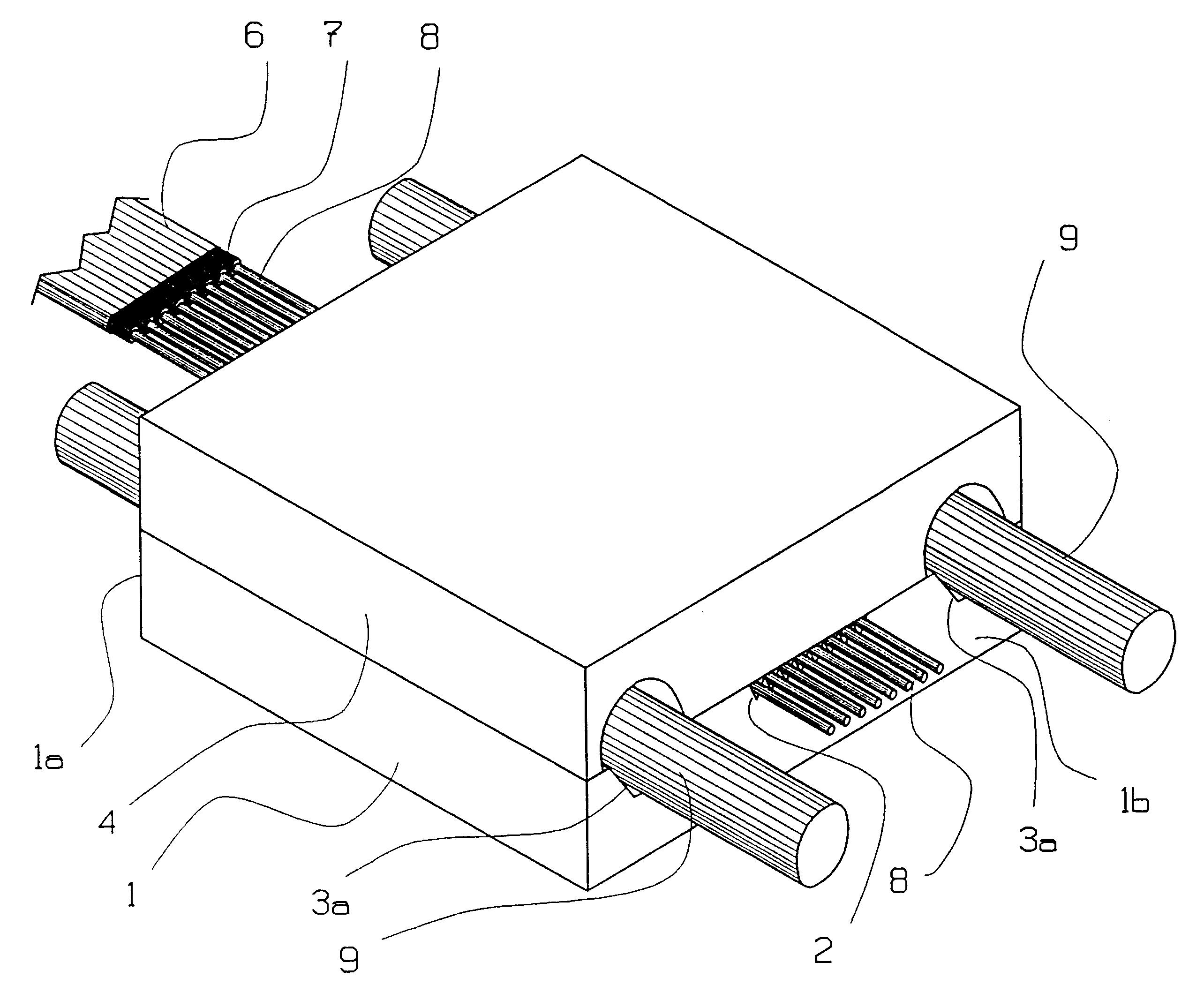
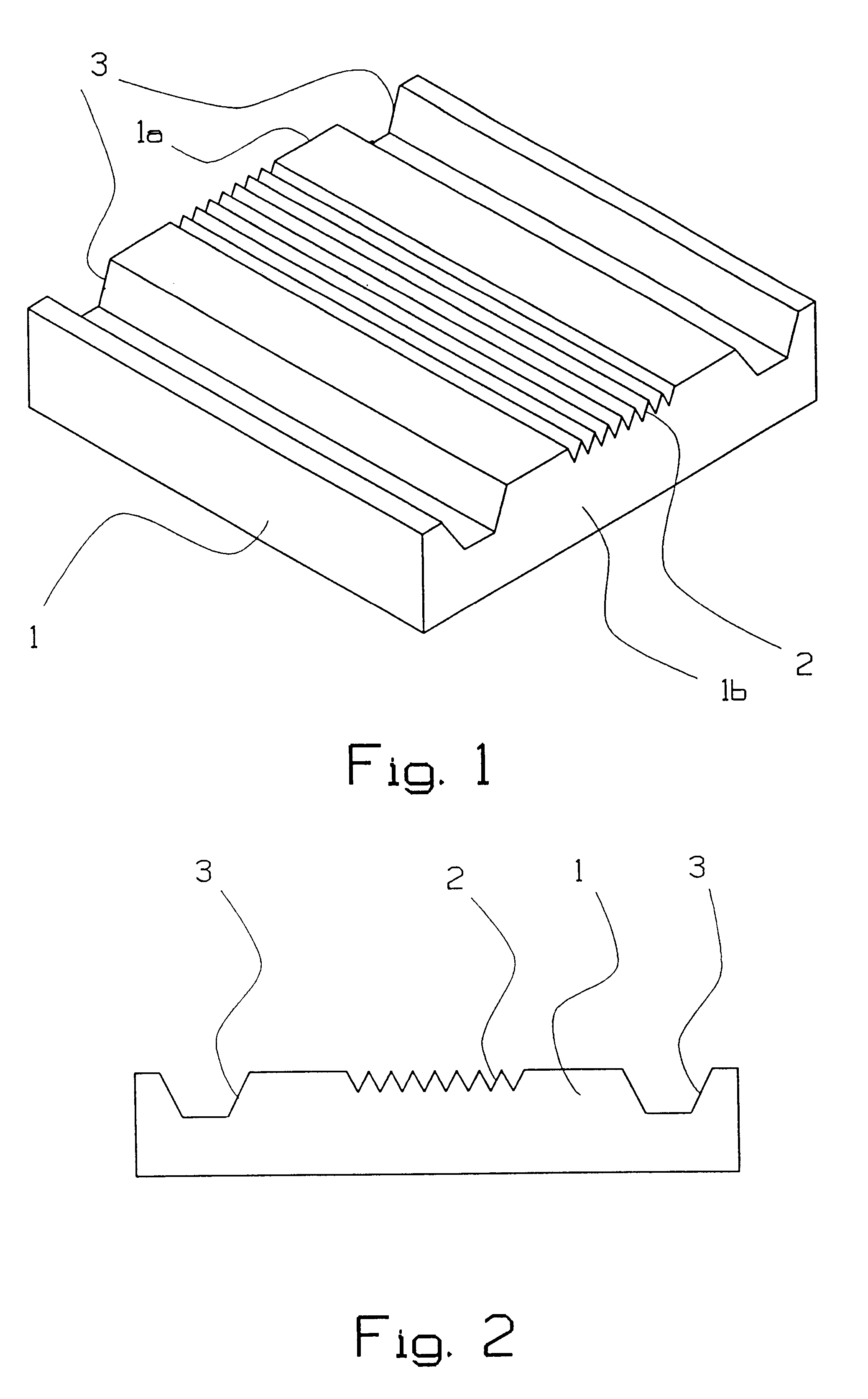
In FIGS. 1 and 2, a high-precision detail or fixture 1 made preferably of silicon is shown in perspective and from one side. The fixture 1 has grooves 2 for optical fibers from e.g. a fibre ribbon cable. In FIGS. 1 and 2 the number of grooves 2 is eight, but can be any arbitrary number. The fixture 1 also has grooves 3 for the guide pins (which are used for the external connection). The grooves 2, 3 can have any arbitrary cross-sectional shape but preferably have a V-shape. The grooves 3 can advantageously have flat bottoms. In the following they will also be referred to as V-grooves. All the V-grooves are straight and parallel and run on the upper side of the fixture from a first fixture side 1a to a second fixture side 1b.

Preferably, several fixtures 1 are manufactured at the same time on a silicon disc. All the V-grooves 2, 3 are defined by one and the same mask, whereafter wet etching takes place. The precision between the V-grooves 2, 3 is ensured this way.

According to the inve...


PUM


Abstract

The present invention relates to a manufacturing method for an opto-mechanical connector (10) and to the connector itself. The invention includes that a fixture (1) is manufactured with straight and parallel grooves (2,3) running on the upper side of the fixture (1) from a first fixture side (1a) to a second fixture side (1b), and which grooves (2,3) are intended partly for optical fibers and partly for guide pins. A lid (4) is attached above the fixture (1), whereafter optical fibers (8) from, for example, a fiber ribbon cable (6) are introduced into the grooves (2) intended for the fibers from the first fixture side (1a) so that the fiber ends (8) extend out through the second fixture side (1b). Guide pins (9) are furthermore introduced into the grooves (3) intended for the guide pins. The structure obtained (fixture (1), lid (4), fiber ends (8) and guide pins (9)) is completely or partially enclosed by a plastic capsule (11).

Description

The present invention relates to a production process for an opto-mechanical connector and to the connector itself.STATE OF THE ARTIn order to reduce the total cost for connecting optical fibers, multifibre connectors are used. The advantage of these is that the time-consuming and therewith costly mounting and supplementary work stages can be performed on several fibers at once.One of the best known embodiments of multifibre connectors is the Japanese so-called MT-connector. This is based upon a precision part made of extruded thermosetting plastic in which the fibers are mounted (glued).In another embodiment of multifibre connectors, an MT-compatible optical connector is extruded directly onto the fibers, see Swedish Patent Application No. 9301858-8. The fibers as well as guide pins are placed and fixed in V-shaped grooves in the cavity of the mould, after which the extrusion takes place. This method means that the gluing operation disappears, which rationalises the production and ...

Claims


Application Information

Patent Timeline
Patent Type & Authority Patents(United States)
IPC IPC(8): G02B6/38G02B6/40
CPCG02B6/3839G02B6/3865G02B6/3885
Inventor STEIJER, ODDMOLL, CHRISTERLINDSTROM, BENGTVIEIDER, CHRISTIANERIKSEN, PAULENGSTRAND, JAN-.ANG.KELARSSON, OLLEELDERSTIG, H.ANG.KAN
Owner TELEFON AB LM ERICSSON (PUBL)
Learn More