
Method and device for measuring and stabilization using signals from a Fabry-Perot

a technology of fabryperot and signal, which is applied in the direction of instruments, electrical equipment, lasers, etc., can solve the problems of high system cost, high optical structure cost, and possible misinterpretation of signals in signal analysis, and achieve low cost, compact structure, and simple structure

Inactive Publication Date: 2001-01-23
MUELLER WIRTS THOMAS
View PDF2 Cites 48 Cited by
  • Summary
  • Abstract
  • Description
  • Claims
  • Application Information

AI Technical Summary

Benefits of technology

The present invention is based on the problem of proposing a method of laser frequency and mode control which allows for a simple, low-cost and compact structure and simultaneously for a high-speed high-precision detection of the laser frequency. This problem is solved by the method defined in claim 1. The signals so obtained can be used to perform a desired high-speed correction of the laser frequency.
It is advantageous to arrange optical lenses in front of the detectors, which furnish a compensation of the beam offset in translation or rotation of the structure relative to the laser beam. With such a design the adjustment of the required 90.degree. phase shift is simple to realize by adjustment of the entire compact structure without any mechanical interference or a degree of freedom of adjustment within the system.

Problems solved by technology

Moreover, misinterpretation may occur in signal analysis as a result of variations of the intensity of the laser light because the measured signals are normally proportional to the intensity.
The essential disadvantage of these systems is the fact that their optical structure consists of a great number of high-quality components.
This involves high costs of the system and a great expenditure incurred for mechanical and thermal stabilization provisions.
Moreover, a compact design is hardly possible.
What is inexpedient in these systems is again the high expenditure incurred by the optical elements, particularly the beam expanders, however mainly the detection rate is strongly restricted by the processing by means of the digital computer and the read-out of the detector array.
Compared against the method proposed here, a further disadvantage consists in the critical dependence on the spatial structure of the beams to be detected, the transverse mode structure.

Method used


Image

  • Method and device for measuring and stabilization using signals from a Fabry-Perot
  • Method and device for measuring and stabilization using signals from a Fabry-Perot
  • Method and device for measuring and stabilization using signals from a Fabry-Perot

Examples


Embodiment Construction

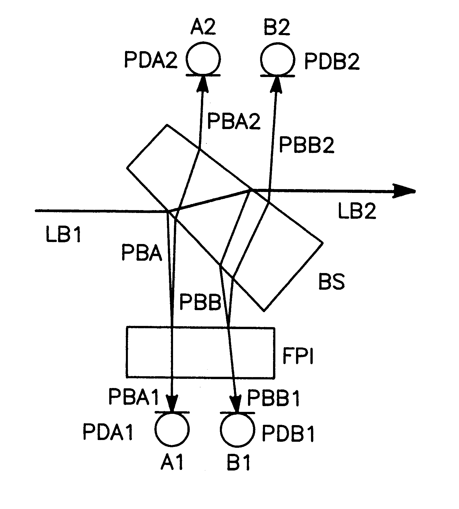
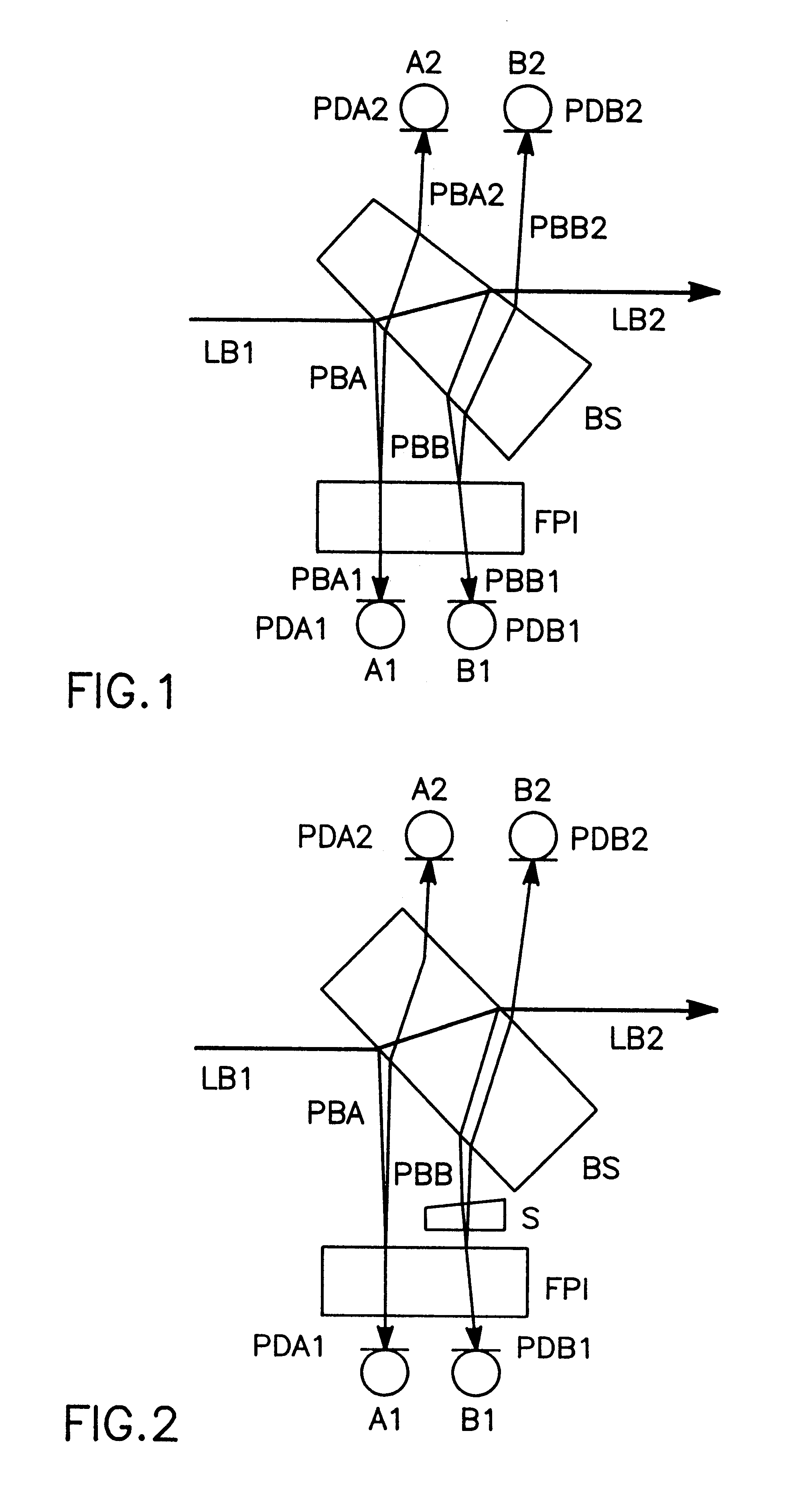
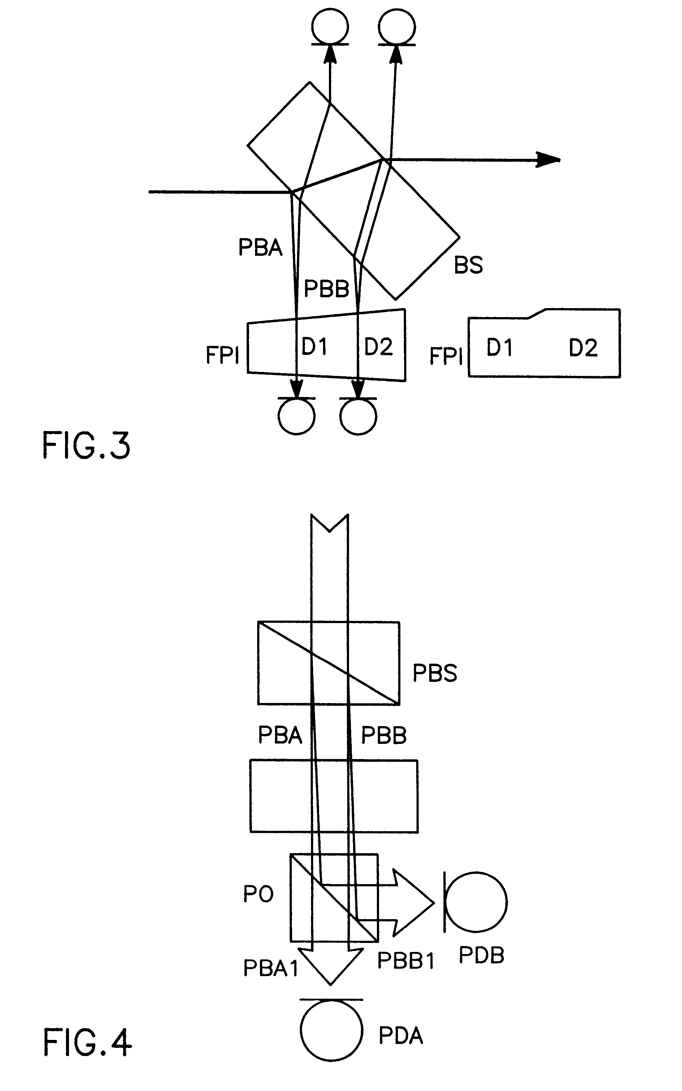
FIG. 1 illustrates a system for realizing the inventive method. The incident laser beam LB1 strikes on a beam splitter BS. The latter is preferably a non-coated glass substrate because for the measuring method only a fraction of the laser radiation is sufficient and a majority of the laser power should still be available in the emerging beam LB2 for the intended application proper. The component PBA reflected from the front surface of the beam splitter now passes through a low finesse etalon FPI. The component beam PBA2 reflected by the etalon is detected by the photodiode PDA2 and converted into the electrical signal A2. This signal has a frequency-dependent profile with a high contrast ratio, however it is proportional to the intensity. The beam PBA1 transmitted by the etalon is converted into the signal A1 by the photodiode PDA1. Then a frequency-independent signal IA proportional to the intensity can be generated from an appropriate electronic summation of the signals A1 and A2,...


PUM


Abstract

For measuring a laser frequency electronic signals can be generated by means of optical interferometers, especially Michelson, Mach-Zehnder and Fabry-Perot interferometers. These signals present profiles with a variation of the laser frequency which are practically identical but shifted in phase by 90°. It is common to generate such phase-shifted signals for frequency measurement in various systems, e.g. by means of a sigmameter, which present, however, disadvantages on account of the great number of the necessary high-quality optical components. The inventive method is based on the analysis of transmission and reflection signals of a Fabry-Perot interferometer (FPI) wherein the signals are obtained from two component beams (PBA and PBB) which are passed through slightly different path lengths within the interferometer. These differences in the length of the optical paths are so selected by different angles of incidence of the component beams into the Fabry-Perot interferometer or by an appropriate shape of the interferometer that the required 90° phase shift is adjusted between the detected intensity signals. From these signals electronic signals can be obtained for detection and also for a rapid correction of the laser frequency.

Description

The invention relates to a method of and a device for laser frequency measurement and stabilization by means of an interferometer, on the basis of the generation of two signals shifted in phase by roughly 90.degree. relative to each other, which signals are obtained from two component beams of the laser beam to be measured.PRIOR ARTAs a function of the intended application of a laser it may be important to maintain the laser frequency at a constant level, to allow for a desired behavior in frequency de-tuning, the so-called scans, or to provide an appropriate possibility to check the scan behavior or the longitudinal single-mode nature of the laser. To this end the use of optical interferometers, particularly Michelson, Mach-Zehnder and Fabry-Perot interferometers, is common for generating an electrical signal varying as the laser frequency varies. On account of the periodic structure of this signal, however, the laser frequency is not yet fixed because the frequency can be determin...

Claims


Application Information

Patent Timeline
IPC IPC(8): G01J9/02G01J9/00H01S3/13
CPCG01J9/02H01S3/1303
Inventor MUELLER-WIRTS, THOMAS
Owner MUELLER WIRTS THOMAS
Learn More