Vehicular damper with vehicle height adjusting function having an internal heat source

Inactive Publication Date: 2001-01-30
HONDA MOTOR CO LTD
View PDF2 Cites 66 Cited by
  • Summary
  • Abstract
  • Description
  • Claims
  • Application Information

AI Technical Summary

Problems solved by technology

As a result, the assembling work of the above-descr

Method used


Image

  • Vehicular damper with vehicle height adjusting function having an internal heat source
  • Vehicular damper with vehicle height adjusting function having an internal heat source

Examples


Embodiment Construction

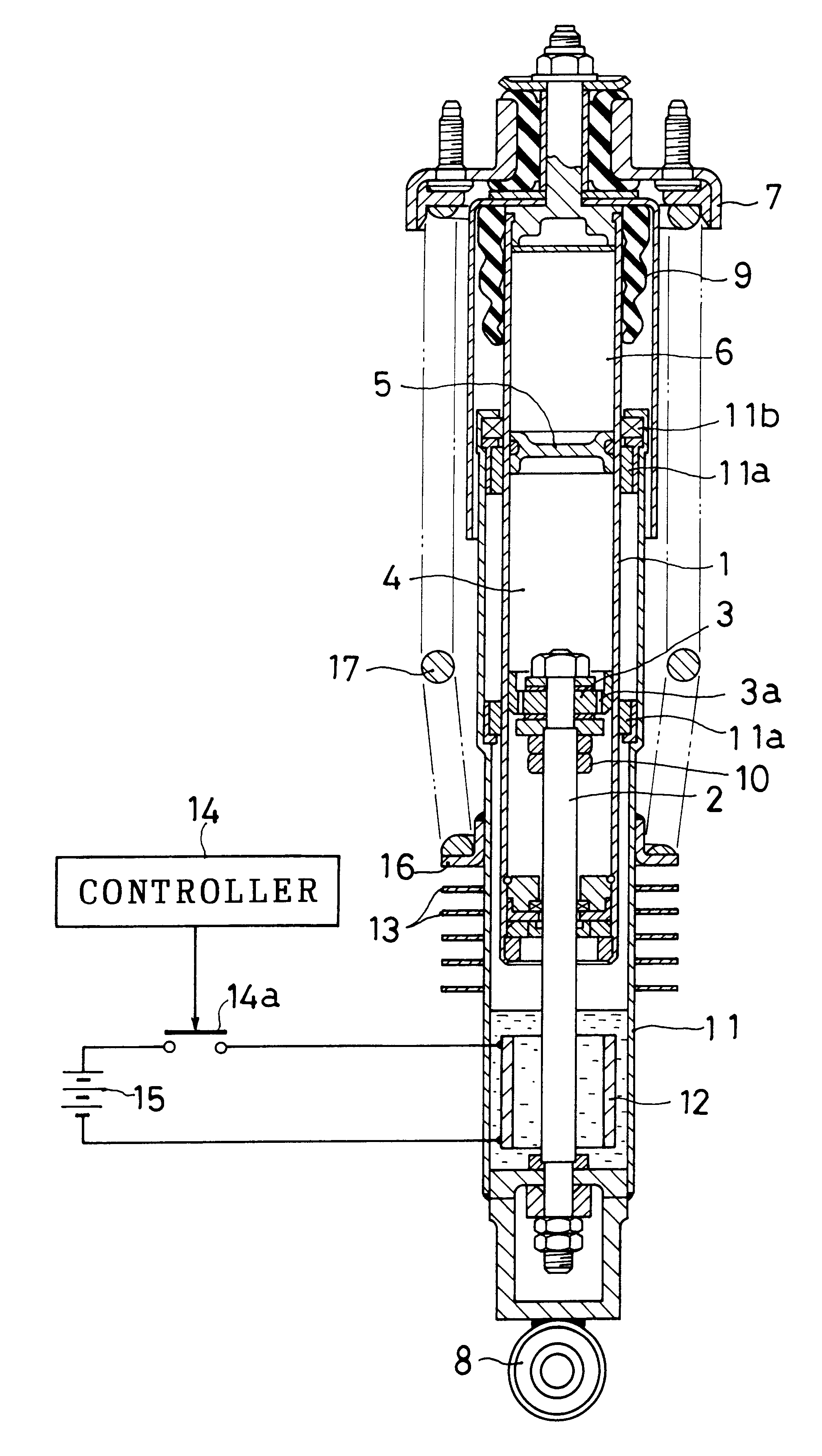
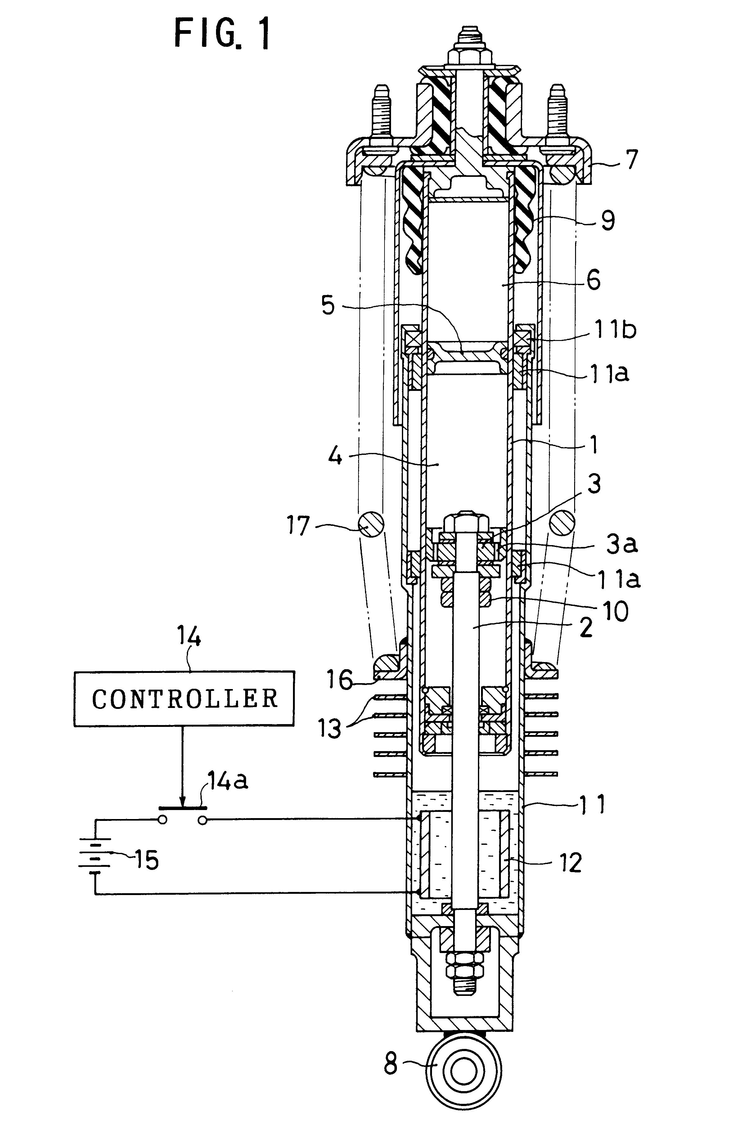
With reference to FIG. 1, reference numeral 1 denotes a damper main body which is made up of a single tube. A damper rod 2 is inserted into the damper main body 1 from the bottom side thereof so as to be movable up and down. On an upper end of the damper rod 2, there is mounted a damper piston 3 having an orifice 3a. The damper main body 1 has formed therein an oil chamber 4 into which the damper piston 3 is inserted, and an upper gas chamber 6 which is partitioned by a free piston 5 relative to the oil chamber 4. As a whole, a mono-tube type of hydraulic damper is thus constituted by the above-described members. The damper main body 1 is connected to a vehicle body via a bracket 7 which is attached to an upper end of the damper main body 1. The damper rod 2 is connected to an unsprung member via a bush 8 which is attached to a lower end of the damper rod 2. It is thus so arranged that a damping force against the vertical vibrations of the unsprung member can be obtained. Further, a...


PUM


Abstract

In a vehicular damper with a vehicle height adjusting function, a pressure source for adjusting the vehicle height is integrally assembled into the damper to improve the ease with which the damper is assembled into a vehicle body. For that purpose, on an outer peripheral portion of a damper main body there is provided a case which is connected to a damper rod and which is vertically movable. A refrigerant which varies between a gaseous phase and a liquid phase is contained in the case in a hermetically sealed manner. An electric heater is disposed inside the case to heat and evaporate the refrigerant by the electric heater. The vehicle height is increased by an increase in the vapor pressure inside the case.

Description

1. Field of the InventionThe present invention relates to a vehicular damper with a vehicle height adjusting function which is applied to a vehicle such as a motor vehicle. In this specification, the term "vehicular damper" means a damper for use in a vehicle.2. Description of the Related ArtA vehicle damper is provided with a damper main body, and a damper rod which is inserted into the damper main body so as to be movable up and down. One of the damper main body and the damper rod is connected to an unsprung member, and the other thereof is connected to a vehicle body so that a damping force against the vibrations of the unsprung member can be obtained.In case a function of adjusting the vehicle height (also called a vehicle height adjusting function) is added to the damper, the following arrangement is conventionally employed. Namely, a cylinder for adjusting the vehicle height is interposed between the vehicle body and the damper. A pressure fluid from a pressure source is suppl...

Claims


Application Information

Patent Timeline
IPC IPC(8): B60G17/00F16F9/00F16F9/06F16F9/44
CPCB60G17/002F16F9/06F16F2222/02
Inventor HAYAKAWA, YUKIONAKAHARA, KIYOSHI
Owner HONDA MOTOR CO LTD
Why Eureka
Try Eureka