
Composite type magnetic head using composite metallic wire

a composite, metal wire technology, applied in the direction of insulated conductors, cables, conductors, etc., can solve the problems of low tensile strength of wires, manual wiring operation, and reducing the efficiency of head operations

Inactive Publication Date: 2001-01-30
NGK INSULATORS LTD
View PDF21 Cites 1 Cited by
  • Summary
  • Abstract
  • Description
  • Claims
  • Application Information

AI Technical Summary

Problems solved by technology

For reducing an inductance of a magnetic head, it is required that a cross sectional area of a magnetic path is reduced, for example, a thickness of a magnetic core is reduced, thereby causing a problem of reducing an efficiency of the head.
However, indeed, a wiring operation is manual, and therefore, a wire having a low tensile strength has problems of the snapping of the wire, and the like.
Accordingly, the wire is required to have a tensile strength of at least 20 g. Therefore, it is difficult to use a thin copper alloy wire as a coil wire from the view point of mass-production.
Accordingly, it is difficult to achieve a memory density of 600 Mb / in.sup.2 or more by using a magnetic head using a wire such as a conventional copper alloy wire.

Method used


Image

  • Composite type magnetic head using composite metallic wire
  • Composite type magnetic head using composite metallic wire
  • Composite type magnetic head using composite metallic wire

Examples


examples 1-11

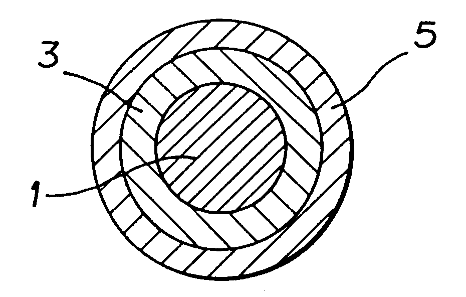
A tungsten wire (inner layer) having a diameter of 15 .mu.m and a length of 1000 m was subjected to electrolytic polishing by a well-known method or a drawing so as to obtain a wire having a diameter of 8-12 .mu.m.

Subsequently, on the obtained wire was formed an outer layer by a electrolytic plating in a well-known method using a copper having a thickness of 1.5-3.5 .mu.m.

Then, an insulating coat made of polyurethane was formed on the outer layer so as to have a thickness of 2.5, 3.0 or 3.5 .mu.m so as to obtain a composite metallic wire having the insulating coat and having a diameter of 19 or 22 .mu.m.

The results are shown in Table 1.

For example, in the case of Example 1, a tungsten wire was subjected to electrolytic polishing to obtain a diameter of 8 .mu.m. Subsequently, the outer layer made of copper having a thickness of 2.5 .mu.m was formed. Then, an insulating coat made of urethane and having a thickness of 3.0 .mu.m was formed on the outer surface so that a composite metall...

reference examples 1-7

Incidentally, a tungsten subjected to only electrolytic polishing was measured for an electric resistance. The results are shown in Table 3.

As shown in Table 3, an electric resistance of 300 .OMEGA. / m or less cannot be obtained by using only an electrolytically polished tungsten.

reference examples 8-12

As a withstand voltage property in a case that a wire is wound around a core chip having a thickness of 35 .mu.m, there were obtained thicknesses of insulating coats each satisfies a condition of over 25 M.OMEGA. at 50 V, over 1000 M.OMEGA. at 100 V, and over 1000 M.OMEGA. at 200 V.

The results are shown in Table 4.

As obvious from Table 4, it is necessary for an insulating coat to have a thickness of 2.5 .mu.m or more. In this case, a composite metallic wire same as in Example 7 was used, and polyurethane was used as an insulating coat.


PUM

PropertyMeasurementUnit
diameteraaaaaaaaaa
diameteraaaaaaaaaa
inductanceaaaaaaaaaa

Abstract

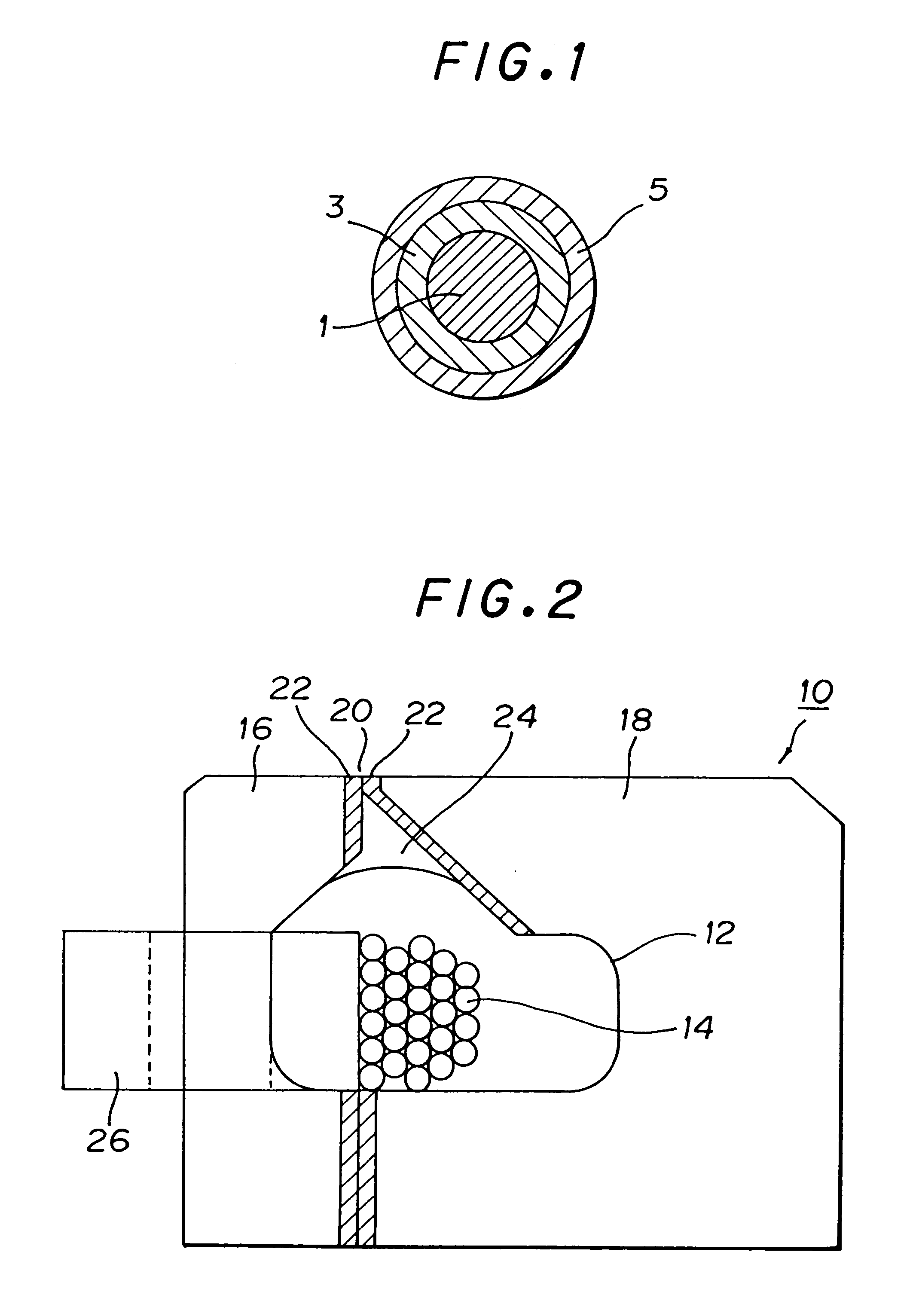
A composite metallic wire includes: an inner layer having a cross-sectional shape of a rough circle; and a metal outer layer having a cross-sectional shape of a rough ring; wherein the composite metallic wire has a diameter of 15 mum or less and an electric resistance of 300 OMEGA / m or less. A composite type magnetic head using as a coil wire a composite wire comprising: (1) a composite metallic wire comprising: an inner layer having a cross-sectional shape of a rough circle; and a metal outer layer having a cross-sectional shape of a rough ring; wherein the composite metallic wire has a diameter of 15 mum or less and an electric resistance of 300 OMEGA / m or less, and (2) an insulating coat provided in the outer periphery of the outer layer.

Description

BACKGROUND OF THE INVENTION AND RELATED ART STATEMENTThe present invention relates to a composite metallic wire which can be suitably used as a coil wire for a composite type magnetic head, particularly, as a coil wire for a high-density magnetic recording head and to a magnetic head using the composite metal wire.With the spread of computers, an increase of a capacity and a speed up of a magnetic recording apparatus have been rapidly improving. Accordingly, a magnetic head is required to have (1) a smaller size and (2) a lower inductance.In order to enlarge a valid recording area and improve a running followability of a magnetic recording apparatus, a slider is changed from one having dimensions of 4.3 mm.times.2.9 mm.times.0.86 mm, which was a standard slider originally, to another one having dimensions of 2.0 mm.times.1.6 mm.times.0.46 mm, which is a main current slider and called "50% slider". Further, a slider called "30% slider" is under investigation.In order to improve a tra...

Claims


Application Information

Patent Timeline
Patent Type & Authority Patents(United States)
IPC IPC(8): B32B15/00H01B1/04H01B1/02G11B5/17H01B5/02H01B7/00H01F27/00
CPCB32B15/00H01B1/04H01B1/02Y10T428/294H01L2224/45572H01L2224/45599H01L2924/01004H01L2924/01025H01L2924/01078H01L2924/01079H01L2924/30107H01L2924/00014Y10T428/2951Y10T428/2944Y10T428/2942Y10T428/2947H01L2224/48G11B5/1274G11B5/17
Inventor TSUNO, NOBUOMATSUZAWA, SOICHIRO
Owner NGK INSULATORS LTD
Learn More