Single-stroke radiation anti-scatter device for x-ray exposure window

a single stroke radiation and radiation anti-scattering technology, applied in the direction of instruments, diaphragms/collimeters, diaphragms for radiation diagnostics, etc., can solve the problems of impracticality of positioning and maintaining the anti-scatter grid, image artifacts may be seen, and the use of a single stroke unidirectional linear velocity profile is impractical

Inactive Publication Date: 2001-01-30
DIRECT RADIOGRAPHY
View PDF21 Cites 51 Cited by
  • Summary
  • Abstract
  • Description
  • Claims
  • Application Information

AI Technical Summary

Problems solved by technology

A problem with using grid, however, is that whenever the X-ray detector resolution is comparable or higher than the spacing of the grid, an image artifact from the grid may be seen.
However, Moire pattern artifacts can be introduced when image capture is accomplished through the direct radiographic process or when film images are digitized.
A problem with the above proposed solution, which uses a static grid, is that it is often impractical to position and to maintain the anti-scatter grid in a desired fixed position relative to the radiation detector array.
Using a single stroke unidirectional linear velocity profile is impractical because as the exposure becomes longer the size of the bucky and the length of the bucky path become far too large to be accommodated in a useful package.
While this is an ingenious solution it also presents certain practical problems, particularly related to the direction change in the bucky movement at the two path ends where the grid movement becomes zero prior to reversing direction.
This solution worked for radiographic film exposure, but does not adequately solve the Moire type problems associated with direct radiography detectors.

Method used


Image

  • Single-stroke radiation anti-scatter device for x-ray exposure window
  • Single-stroke radiation anti-scatter device for x-ray exposure window
  • Single-stroke radiation anti-scatter device for x-ray exposure window

Examples


Embodiment Construction

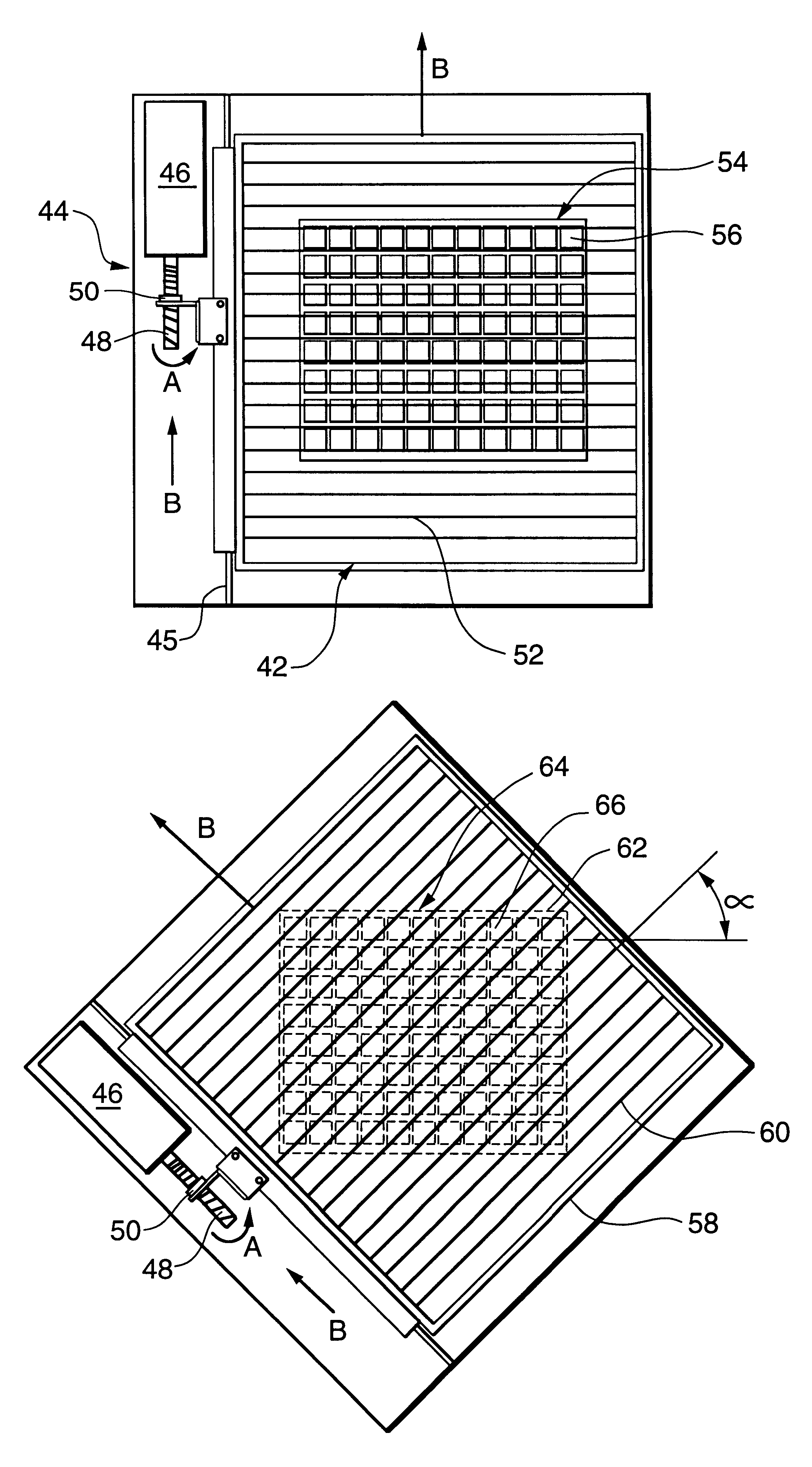
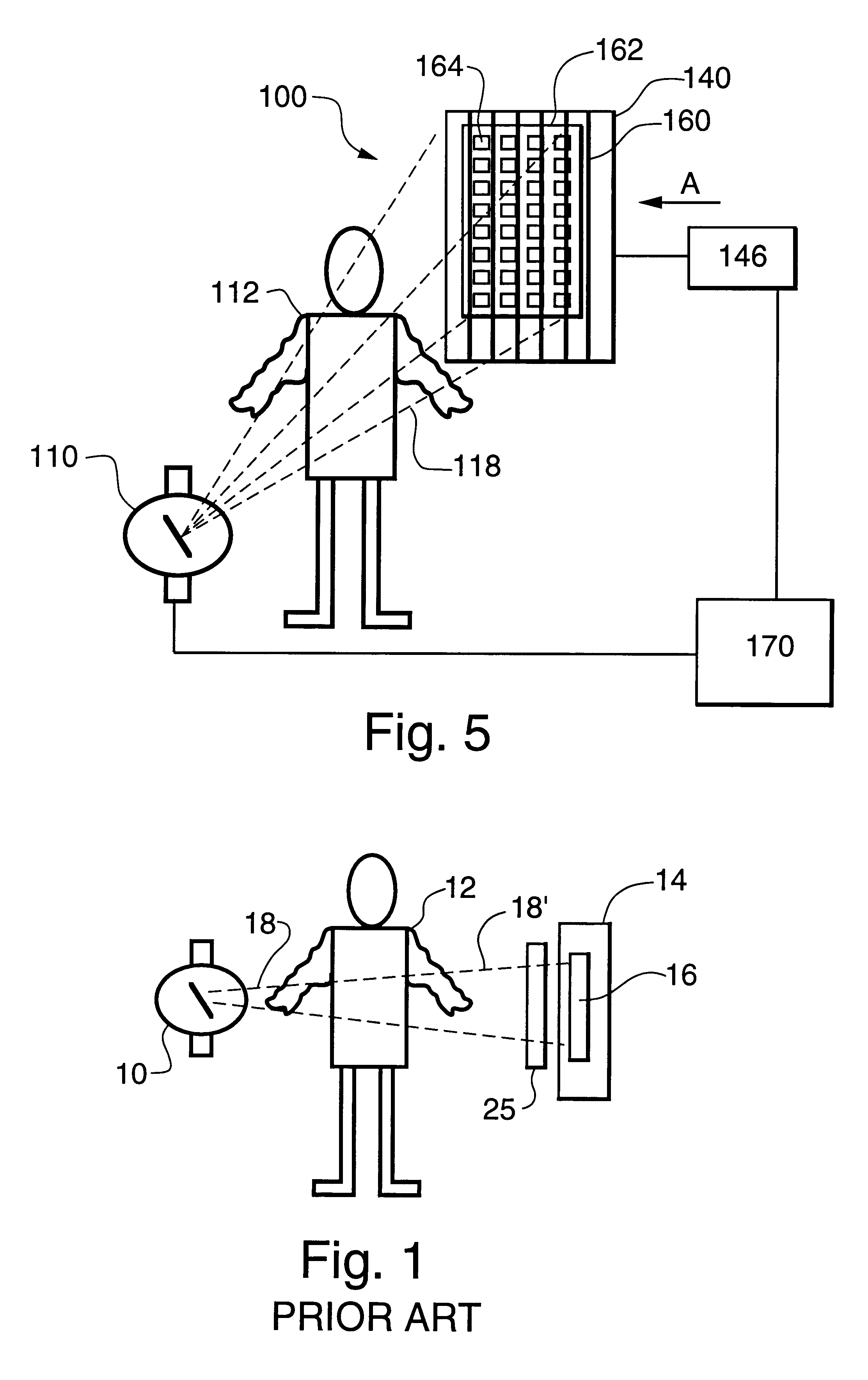
The invention will next be illustrated with reference to the figures wherein similar numbers indicate the same elements in all figures. Such figures are intended to be illustrative rather than limiting and are included herewith to facilitate the explanation of the apparatus of the present invention.

FIG. 1 shows a schematic arrangement in which a source of X-ray radiation 10 provides a beam 18 of X-rays. A target 12 (i.e. a patient in the case of medical diagnostic imaging) is placed in the X-ray beam path. The radiation emerging through patient 12 is intensity modulated because of the different degrees of X-ray absorption in various parts of the patient's body. Cassette enclosure 14, containing radiation sensor 16, intercepts the modulated X-ray radiation beam 18'. Radiation detector 16 absorbs X-rays that penetrate the cassette enclosure 14, and produces a digital image in accordance with the above-referenced patent.

A radiation anti-scatter device 20, known in the art as a bucky, c...


PUM


Abstract

A radiation anti-scatter device comprising a grid and a grid driver connected to the grid for unidirectionaly moving the grid with a variable grid velocity along a path between a starting and an end position, and a method of providing such grid motion. The variable grid velocity may have a velocity profile V1=k1t for a first period and then V2=k2t-m for a second period, where V1 and V2 are velocity, k1 and k2 are constants, t is time, and m is an exponent having a value greater than 0. The anti-scatter device may be a component of a direct radiographic diagnostic imaging system which includes an image-producing element having an array of radiation detectors aligned in rows, and where the anti-scatter device is a grid having vanes oriented at an angle to the detector rows. Radiation emission may be synchronized with the grid motion to optimize a radiograph for a particular grid, radiation source, or examination procedure. The apparatus implements a method for reducing Moiré patterns in radiographic detectors having an array of sensors by unidirectionaly moving the grid in a single stroke during the radiation exposure with an asymptotically decreasing speed profile such that grid motion is maintained for a plurality of different radiation exposure times.

Description

This invention relates to radiation anti-scatter grids, and more particularly, to a single stroke, moving radiation anti-scatter grid that is a component in a radiographic diagnostic imaging system, specifically a direct radiographic imaging system.Description of the ArtDirect radiographic imaging using detectors comprising a two dimensional array of tiny sensors to capture a radiation generated image is well known in the art. The radiation is imagewise modulated as it passes through an object having varying radiation absorption areas. Information representing an image is, typically, captured as a charge distribution stored in a plurality of charge storage capacitors in individual sensors arrayed in a two dimensional matrix.X-ray images are decreased in contrast by X-rays scattered from objects being imaged. Anti-scatter grids have long been used (Gustov Bucky, U.S. Pat. No. 1,164,987 issued 1915) to absorb the scattered X-rays while passing the primary X-rays. A problem with using ...

Claims


Application Information

Patent Timeline
Patent Type & Authority Patents(United States)
IPC IPC(8): G21K1/02A61B6/06G01T1/00G01T7/00
CPCG21K1/025
Inventor LEE, DENNY L. Y.GOLDEN, KELLY P.
Owner DIRECT RADIOGRAPHY
Why Eureka
Try Eureka